|
| |
TM 9-2320-364-34-4
23-100
23-16. CENTER SUPPORT REPAIR (CONT).
(6)
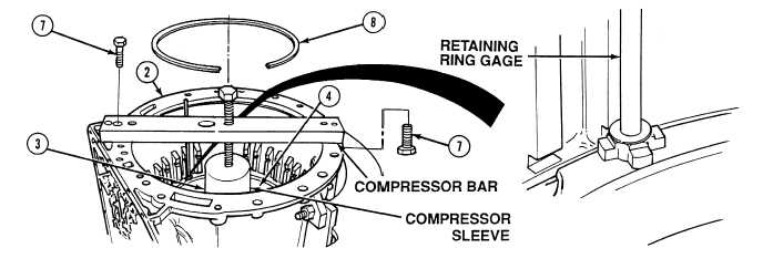
Install compressor sleeve on center support (3).
(7)
Position compressor bar across transmission housing (2) and secure with two screws (7).
(8)
Tighten compressor bar center screw to 60 lb-in (7 N.m) to compress center support housing (4).
(9)
Using retaining ring gage, measure retaining ring (8) opening with each of four lugs of retaining ring
gage. This will determine retaining ring size. Select thickest retaining ring (8) that will fit into groove of
transmission housing (2).
Retaining Ring Color Code
Size
Blue retaining ring
0.148 to 0.150 in. (3.759 to 3.810 mm) thick
Yellow retaining ring
0.152 to 0.154 in. (3.861 to 3.912 mm) thick
Red retaining ring
0.158 to 0.160 in. (4.013 to 4.064 mm) thick
Use care when installing retaining rings. Retaining rings are under tension and can act as
projectiles when released causing injury to personnel.
NOTE
Retaining ring to be installed in Step (10) is same retaining ring which was selected in Step (9).
(10)
Install retaining ring (8) in transmission housing (2). Turn retaining ring (8) until split in retaining ring
faces opposite side of oil pan.
|