|
| |
TM 9-2320-364-34-4
24-12
Materials/Parts
Grease (Item 26, Appendix B)
Sealing Compound (Item 53, Appendix B)
This task covers:
a. Removal
b. Installation
c.
Follow-On Maintenance
INITIAL SETUP
Equipment Condition
Neutral start switch removed, (Para 24-5)
Tools and Special Tools
Tool Kit, General Mechanic’s
(Item 240, Appendix F)
24-6. SPEEDOMETER SENSOR REPLACEMENT.
Materials/Parts-Continued
Bearing, Thrust (Item 17, Appendix E)
Spring (Item 661, Appendix E)
Washer (Item 689, Appendix E)
a.
Removal.
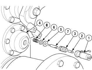
(1)
Remove sending unit (1) and tang (2) from
sleeve (3).
Speedometer shaft may come out
when sleeve is removed or may
stay with bearing cap. Be careful
so parts are not dropped into
transfer case housing. Failure to
comply may result in damage to
equipment.
(2)
Remove sleeve (3) from bearing cap (4).
(3)
Remove thrust bearing (5), washer (6),
speedometer shaft (7) and spring (8) as an
assembly from bearing cap (4). Discard
thrust bearing, washer and spring.
NOTE
Perform Step (4) only if tang is
damaged.
(4)
Remove tang (2) from sending unit (1).
Discard tang.
|