|
| |
TM 9-2320-364-34-4
24-37
(51)
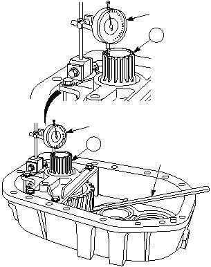
Position dial indicator on differential shaft
assembly (57).
(52)
While using pry bar to lift differential shaft
assembly (57) as far as possible, measure end
play and record deflection on dial indicator.
(53)
If end play deflection is 0.003 to 0.006 in.
(0.076 to 0.152 mm), correct number of shims
are installed. Go to Step (62).
NOTE
If deflection is not within
specifications, perform
Steps (55) through (61).
(54)
If deflection is less than 0.003 in.
(0.076 mm), shims must be added below
front shaft assembly. If deflection is more
than 0.006 in. (0.152 mm), shims must be
removed.
(55)
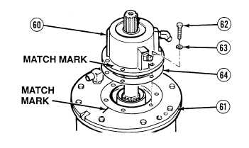
Matchmark front shaft assembly (60) and
cover enclosure (61).
(56)
Remove six screws (62) and lockwashers
from cover enclosure (61). Discard
lockwashers.
(57)
Remove front shaft assembly (60) from
cover enclosure (61).
(58)
Remove shims (64) from cover
enclosure (61) or front shaft assembly (60).
(59)
Add or remove shims (64) to stack to equal
proper thickness.
(60)
Repeat Steps (38) through (42) and install
front shaft assembly (60).
(61)
Repeat Steps (50) through (59) and check
and adjust end play on differential shaft
assembly (57).
57
PRY BAR
DIAL INDICATOR
DIAL
INDICATOR
57
|