|
| |
TM 9-2320-364-34-4
20-14
Materials/Parts
Tags, Identification (Item 72, Appendix B)
This task covers:
a. Removal
b. Follow-On Maintenance
INITIAL SETUP
Tools and Special Tools - Continued
Wrench, Combination 1-3/4 in.
(Item 263, Appendix F)
Equipment Condition
Exhaust manifolds removed, (Para 20-3)
Tools and Special Tools
Tool Kit, General Mechanic’s
(Item 240, Appendix F)
Connector Remover (Item 42, Appendix F)
Pan, Drain 4 gal (Item 144, Appendix F)
Wrench, Combination 1-1/8 in.
(Item 255, Appendix F)
Wrench, Combination 1-1/4 in.
(Item 256, Appendix F)
Wrench, Combination 1-1/2 in.
(Item 260, Appendix F)
20-4. ELECTRONIC CONTROL MODULE (ECM) REMOVAL.
a.
Removal
NOTE
PLS has two types of engines, DDEC II and DDEC III. Both are same, except where
noted.
DDEC II ECM has all multiple connectors on right side.
DDEC III ECM has multiple connectors on both sides.
Remove cable ties as required.
Tag and mark wires and connectors prior to removal.
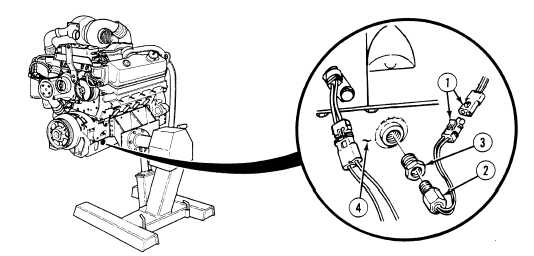
(1)
Disconnect MC70 connector (1).
(2)
Remove engine oil temperature sensor (2) from adapter (3).
(3)
Remove adapter (3) from oil pan (4).
|