|
| |
TM 9-2320-364-34-4
25-50
25-12. AXLE NO. 1, 2 AND 5 PIVOT AND SPINDLE/TRUNNION BEARING
ASSEMBLY REPAIR (CONT).
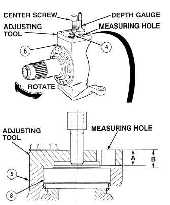
NOTE
Measure distance through
measuring hole.
(22)
Using depth gage, measure the distance from
top of adjusting tool to top of pivot and
spindle assembly (5) and record as
dimension “A”.
(23)
Using depth gage, measure distance from
top of adjusting tool to top of trunnion (8)
and record as dimension “B”.
(24)
Subtract dimension “A” from dimension “B”
(B – A). The answer is the gap between
pivot and spindle assembly (5) and top of
trunnion (8).
(25)
Refer to Table 25-3 to determine shim
thickness.
(26)
Remove screws (4) and adjusting tool.
(27)
Rotate pivot and spindle assembly (5) to
centered position.
Table 25-3. Determining Shim Thickness
Gap between pivot and spindle
assembly and trunnion
Shim thickness
0.018 to 0.022 in. (0.457 to 0.559 mm)
0.016 in. (0.406 mm)
0.022 to 0.026 in. (0.559 to 0.660 mm)
0.020 in. (0.508 mm)
0.026 to 0.030 in. (0.660 to 0.762 mm)
0.024 in. (0.610 mm)
0.030 to 0.033 in. (0.762 to 0.838 mm)
0.028 in. (0.711 mm)
0.033 to 0.037 in. (0.838 to 0.940 mm)
0.031 in. (0.787 mm)
0.037 to 0.041 in. (0.940 to 1.041 mm)
0.035 in. (0.889 mm)
0.041 to 0.045 in. (1.041 to 1.143 mm)
0.039 in. (0.991 mm)
|