|
| |
TM 9-2320-364-34-4
25-64
25-15. AXLE NO. 1 AND 5 DIFFERENTIAL ASSEMBLY REPAIR (CONT).
b.
Disassembly.
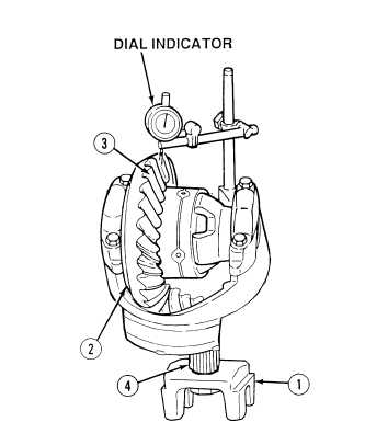
Make sure pinion shaft does not move while backlash is being measured or incorrect
reading will result.
(1)
With the aid of an assistant, hold yoke (1)
while turning differential gear (2)
counterclockwise until gear stops to take up
backlash.
NOTE
Shaft from dial indicator must be
at right (90 degree) angle to face
of tooth when in contact.
(2)
Install dial indicator on differential gear
face (3).
(3)
Turn differential gear (2) clockwise until it
stops.
NOTE
Record differential gear to
pinion shaft backlash and
contact pattern. Backlash
should be 0.010 to 0.016 in.
(0.254 to 0.406 mm).
(4)
Check differential gear (2) to pinion
shaft (4) backlash as measured on dial
indicator and contact pattern.
NOTE
Turn differential assembly
90 degrees.
(5)
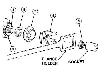
Unstake adjusting nut (5) from pinion
shaft (4).
(6)
With the aid of an assistant and using flange
holder and socket, remove adjusting nut (5)
from pinion shaft (4). Discard adjusting nut.
(7)
Remove flange assembly (6) from pinion
shaft (4).
(8)
Separate dust cover (7) from flange
assembly (6).
(9)
Remove oil seal (8) from axle housing (9).
Discard oil seal.
|