|
| |
TM 9-2320-364-34-4
25-133
(20)
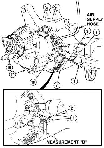
Connect air supply hose to locking cylinder
(7).
(21)
Using air supply hose apply air pressure 100
120 psi (690 to 827 kPa) to locking cylinder
NOTE
When locking cylinder engages
both hub gears will turn in
opposite directions, while
rotating one wheel.
(22)
Turn flange assembly (15) back and forth
until locking cylinder (7) engages.
(23)
Turn screw (1) slowly until screw contacts
fork (18) in differential (17).
(24)
Using dial caliper, measure distance between
face of washer (2) and top of locking
cylinder (7) and record as measurement “B”.
(25)
Determine shim (3) thickness. Shim
thickness is: measurement “B” – 0.004 to
0.020 in. (0.102 to 0.508 mm).
(26)
Remove screw (1) and washer (2).
NOTE
Shim thickness is determined in
Step (25).
(27)
Install shim (3), washer (2) and screw (1) on
locking cylinder (7). Tighten screw to 25 to
32 lb-ft (34 to 43 N.m).
(28)
Remove air supply hose from locking
cylinder (7).
c.
Follow-On Maintenance:
Install brake assembly, (Para 25-21).
END OF TASK
|