|
| |
TM 9-2320-364-34-4
25-138
Materials/Parts
Wire (Item 77, Appendix B)
This task covers:
a. Removal
b. Installation
c. Follow-On Maintenance
INITIAL SETUP
Personnel Required
Two
Equipment Condition
Axle No. 3 or 4 spindle removed, (Para 25-24)
Tools and Special Tools
Tool Kit, General Mechanic’s
(Item 240, Appendix F)
25-25. AXLE NO. 3 AND 4 SHAFTS REPLACEMENT.
a
Steps (1) and (2) keep clutch gear from disengaging after axle shafts are removed. Failure
to perform Steps (1) and (2) makes assembly difficult and could damage parts.
NOTE
Steps (1) and (2) are for the left side axle shaft only.
Screw used in Step (2) was removed with locking cylinder.
(1)
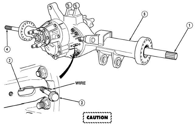
With the aid of an assistant, turn axle shaft (1) slowly, while pulling outward on fork (2).
(2)
Install screw (3) and form a wire hook around fingers of fork (2) and anchor wire with screw (3).
(3)
Pull axle shafts (1) and (4) from axle housing (5).
|