|
| |
TM 9-2320-364-34-4
25-163
Differential and bevel gear
weighs 70 lbs (32 kg). Attach a
suitable lifting device prior to
installation to prevent possible
injury to personnel.
(27)
Attach lifting device to differential gear (3).
(28)
Install differential gear (3) in housing (26).
(29)
Remove lifting device from differential
gear (3).
NOTE
Perform Step (30) if locating
pins were removed.
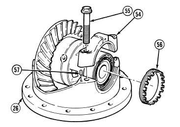
(30)
Install four locating pins (57) in
housing (26).
(31)
Install adjusting nut (56), two bearing
caps (54) and four screws (55). Tighten
screws to 25 lb-in (3 N.m).
(32)
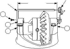
Install differential preload adapter on
bearing cap (54) with screw (52).
(33)
Position dial indicator base on bearing
cap (54) and indicator end on differential
preload adapter.
NOTE
Steps (34) and (36) adjust
bearing preload.
(34)
Tighten adjusting nut (56) to obtain a dial
indicator reading of 0.014 to 0.018 in. (0.356
to 0.457 mm).
(35)
Remove screw (52), dial indicator and
differential preload adapter from bearing
cap (54).
DIFFERENTIAL
PRELOAD
ADAPTER
DIAL
INDICATOR
DISTANCE
BETWEEN
BEARING CAPS
54
54
52
56
|