|
| |
TM 9-2320-364-34-4
25-180
25-28. AXLE NO. 3 DIFFERENTIAL ASSEMBLY REPAIR (CONT).
Adhesives, solvents and sealing
compounds can burn easily, can
give off harmful vapors and are
harmful to skin and clothing. To
avoid injury or death, keep away
from open fire and use in a well-
ventilated area. If adhesive,
solvent, or sealing compound
gets on skin or clothing, wash
immediately with soap and
water.
(25)
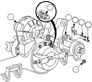
Coat mating surfaces of rear output
assembly (2) and differential housing (6)
with adhesive.
(26)
Coat threads of six screws (3) and screw (4)
with sealing compound.
(27)
Install rear output assembly (2) on
differential assembly (6) with six screws (3).
Tighten screws to 61 to 80 lb-ft (83 to 108
N.m).
(28)
Install screw (4) and bracket (5) on rear
output assembly (2). Tighten screw to 61 to
80 lb-ft (83 to 108 N.m).
(29)
Turn nut (10) until it contacts rear output
assembly (2).
(30)
Install nut (1). Tighten nut to 128 to 150
lb-ft (174 to 203 N.m).
(31)
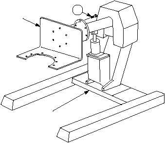
With the aid of an assistant, remove six
screws (17) and differential adapter from
engine stand.
f.
Follow-On Maintenance:
Install Axle No. 3 rear flange assembly, (Para 25-26).
END OF TASK
17
DIFFERENTIAL
ADAPTER
ENGINE
MAINTENANCE
STAND
2
5
4
3
6
1
10
10
|