 |
|||
|
|
|||
|
Page Title:
REAR MARKER LIGHT(S) DO NOT OPERATE. (Cont) |
|
||
| ||||||||||
|
|
 TM 9-2330-385-14
Remove all jewelry such as rings, dog tags, bracelets, etc. If jewelry or tools contact positive electrical
S
circuits, a direct short may result. Damage to equipment, injury, or death to personnel may occur.
Resistors mounted on exterior of junction box assembly reach very high temperatures when power is
S
applied to circuit. Avoid touching or contacting resistors when working in or around junction boxes.
Failure to comply could result in injury to personnel.
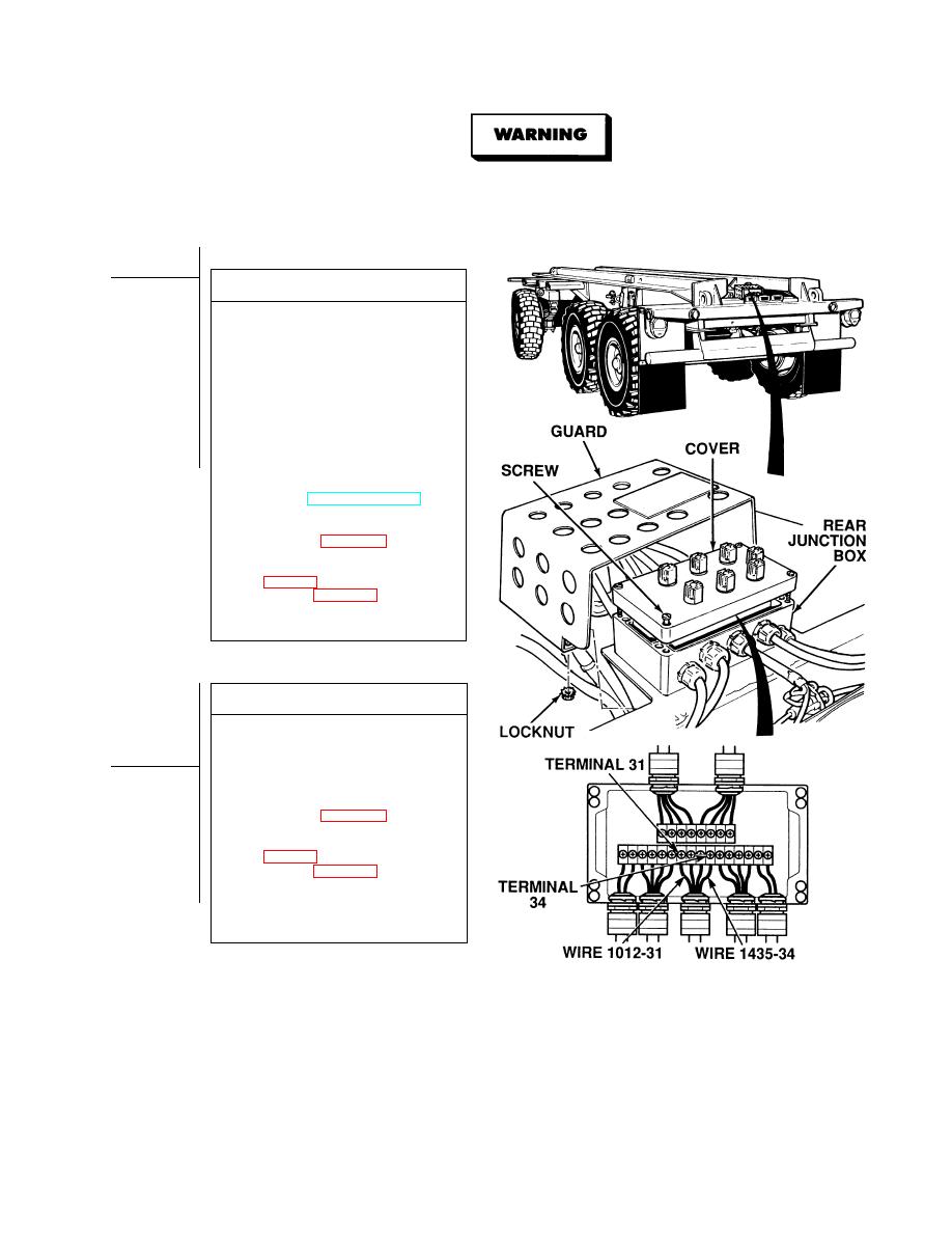
VOLTAGE TEST
(1) Remove four locknuts and rear
junction box guard. Discard
locknuts.
(2) Loosen four captive screws and
remove rear junction box.
(3) Set multimeter select switch to
volts dc.
(4) Connect positive (+) multimeter lead
to rear junction box, terminal 31.
(5) Connect negative (--) multimeter lead
to a known good ground.
(6) While assistant turns ON ENGINE
switch and turns on lights, observe
multimeter (TM 9-2320-364-10).
(a) If 22 to 28 vdc are not present,
replace rear junction box
assembly (Para 4-26).
(b) If 22 to 28 vdc are present, repair
wire 1012-31 (see schematic,
harness (Para 4-30).
(7) Turn off lights and turn OFF ENGINE
switch.
CONTINUITY TEST
(1) Set multimeter select switch to ohms.
(2) Is there continuity between rear
junction box terminal 34 and a known
good ground?
(a) If there is no continuity,
replace rear junction box
assembly (Para 4-26).
(b) If there is continuity, repair
wire 1435-34 (see schematic,
harness (Para 4-30).
(3) Install junction box cover and tighten
four captive screws.
(4) Install rear junction box guard and
four locknuts.
|
|
Privacy Statement - Press Release - Copyright Information. - Contact Us |
