 |
|||
|
|
|||
|
Page Title:
STOPLIGHT DOES NOT OPERATE. (Cont) |
|
||
| ||||||||||
|
|
 TM 9-2330-385-14
Remove all jewelry such as rings, dog tags, bracelets, etc. If jewelry or tools contact positive electrical
S
circuits, a direct short may result. Damage to equipment, injury, or death to personnel may occur.
Resistors mounted on exterior of junction box assembly reach very high temperatures when power is
S
applied to circuit. Avoid touching or contacting resistors when working in or around junction boxes.
Failure to comply could result in injury to personnel.
VOLTAGE TEST
(1) Remove four locknuts and rear
junction box guard. Discard
locknuts.
(2) Loosen four captive screws and
remove rear junction box.
(3) Connect positive (+) multimeter lead
to rear junction box, terminal 17.
(4) Connect negative (--) multimeter lead
to a known good ground.
(5) While assistant fully applies brake
pedal, observe multimeter.
(a) If 22 to 28 vdc are not present,
release brake pedal, and repair
wire 1003-17 (see schematic, Fig
(b) If 22 to 28 vdc are present,
wire 1003-17 is OK.
(6) Release brake pedal.
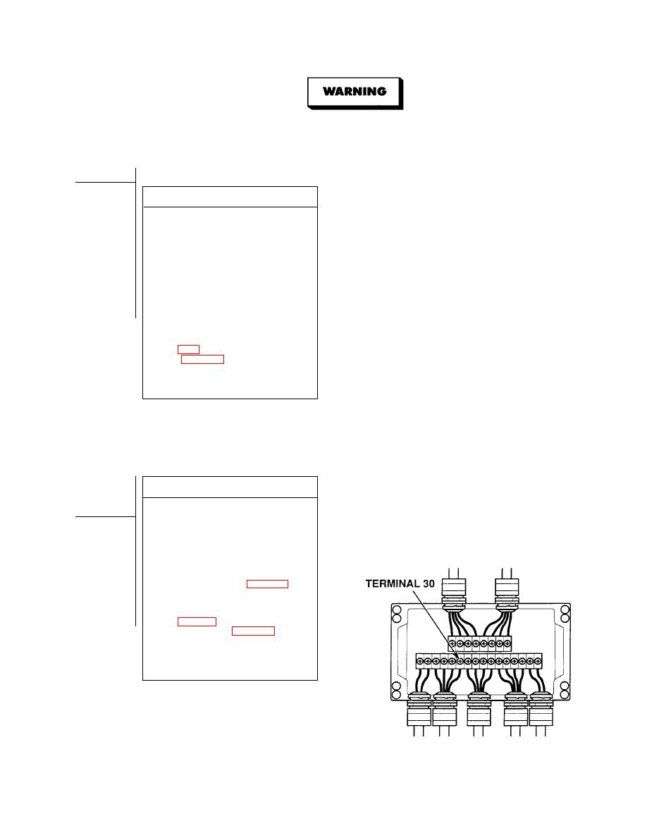
VOLTAGE TEST
(1) Connect positive (+) multimeter lead
to rear junction box, terminal 30.
(2) Connect negative (--) multimeter lead
to a known good ground.
(3) While assistant fully applies brake
pedal, observe multimeter.
(a) If 22 to 28 vdc are not present,
release brake pedal and replace
rear junction box (Para 4-26).
(b) If 22 to 28 vdc are present,
release brake pedal and repair
wire 1004/22-30 (see schematic,
light harness (Para 4-30).
(4) Install rear junction box cover and
tighten four captive screws.
(5) Install rear junction box guard and
four locknuts.
|
|
Privacy Statement - Press Release - Copyright Information. - Contact Us |
