 |
|||
|
|
|||
|
Page Title:
BLACKOUT TAILLIGHT(S) DO NOT OPERATE. (Cont) |
|
||
| ||||||||||
|
|
 TM 9-2330-385-14
Remove all jewelry such as rings, dog tags, bracelets, etc. If jewelry or tools contact positive electrical
circuits, a direct short may result. Damage to equipment, injury, or death to personnel may occur.
CONTINUITY TEST
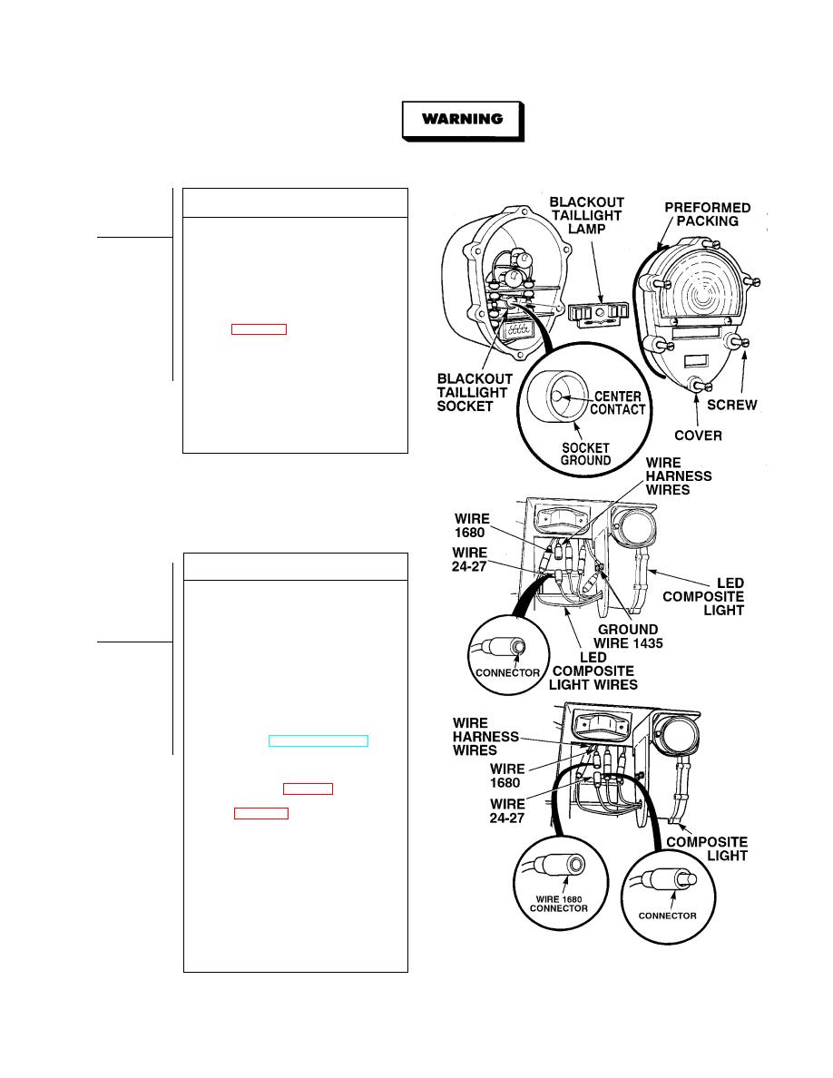
(1) Disconnect wire 1680/24-27 connector
at blackout taillight connector.
(2) Set multimeter select switch to ohms.
(3) Is continuity measured on center
contact of blackout taillight socket and
connector?
(a) If there is no continuity,
replace rear composite light
(b) If there is continuity, blackout
taillight is OK.
(4) Install blackout taillight lamp by
depressing screw in center of
blackout taillight lamp and turning
clockwise.
(5) Install preformed packing and
composite light cover, and tighten six
captive screws.
VOLTAGE TEST
(1) Set multimeter select switch to
volts dc.
(2) If LED composite lights are installed,
disconnect wire 1680/24-27.
(3) Connect positive (+) multimeter lead
to wire 1680/24-27 at blackout taillight
connector.
(4) Connect negative (--) multimeter lead
to a known good ground.
(5) While assistant turns ON ENGINE
switch and turns on BLACKOUT
LIGHTS selector switch, observe
multimeter (TM 9-2320-364-10).
(a) If 22 to 28 vdc are not present,
perform Steps (6) and (7) below
and repair wire 1680/24-27 (see
schematic, Fig FO-1) or replace
composite light harness
(b) If 22 to 28 vdc are present and
composite lights are installed,
wire 1680/24-27 is OK.
(c) If 22 to 28 vdc are present and
LED composite lights are installed,
replace LED composite light
(Para (4-29).
(6) Turn off BLACKOUT LIGHTS selector
switch.
(7) Turn OFF ENGINE switch.
(8) Connect wire 1680/24-27 connector to
blackout taillight connector.
|
|
Privacy Statement - Press Release - Copyright Information. - Contact Us |
