 |
|||
|
|
|||
|
Page Title:
BLACKOUT TAILLIGHT(S) DO NOT OPERATE. (Cont) |
|
||
| ||||||||||
|
|
 TM 9-2330-385-14
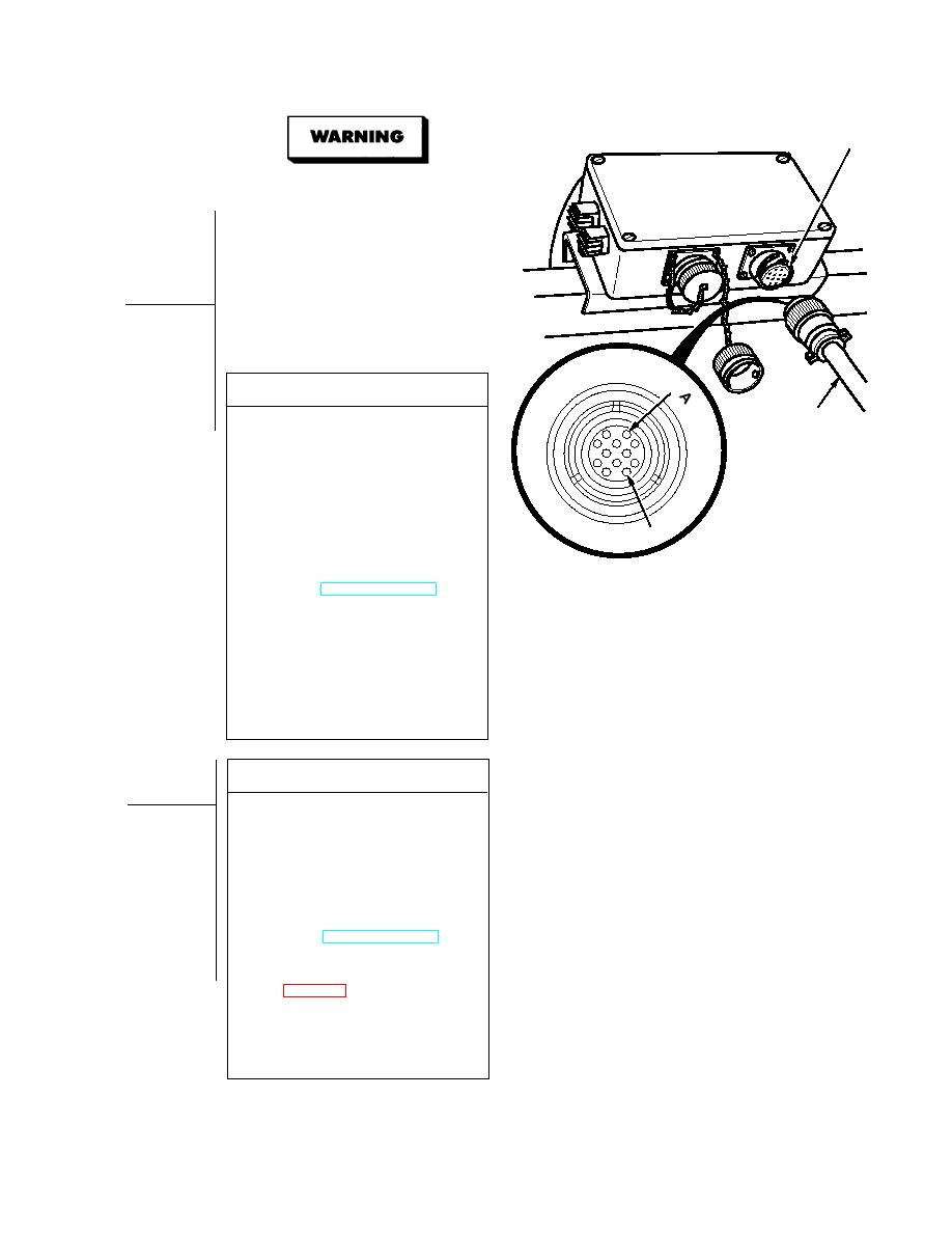
CONNECTOR
MC 15
Remove all jewelry such as rings, dog tags,
S
bracelets, etc. If jewelry or tools contact
positive electrical circuits, a direct short
may result. Damage to equipment, injury, or
death to personnel may occur.
Resistors mounted on exterior of junction box
S
assembly reach very high temperatures when
power is applied to circuit. Avoid touching
or contacting resistors when working in or
around junction boxes. Failure to comply
could result in injury to personnel.
PIN
VOLTAGE TEST
24 VDC
(1) Disconnect 24 vdc (12 terminal) cable
CABLE
from front junction box
J
A
K
B
H
connector MC15.
L
N
(2) Set multimeter select switch to volts
C
M
F
E
D
DC.
(3) Connect positive (+) multimeter lead
to terminal A on trailer end connector.
(4) Connect negative (--) multimeter lead
to terminal D on trailer end connector.
PIN D
(5) While assistant turns ON ENGINE
switch and turns on BLACKOUT
LIGHTS selector switch, observe
multimeter (TM 9-2320-364-10).
(a) If 22 to 28 vdc are not present,
perform Steps (6) and (7) below
and replace 24 vdc cable.
(b) If 22 to 28 vdc are present, 24 vdc
cable is OK.
(6) Turn off BLACKOUT LIGHTS selector
switch.
(7) Turn OFF ENGINE switch.
(8) Connect 24 vdc cable to front junction
box connector MC15.
VOLTAGE TEST
(1) Loosen four captive screws and
remove front junction box cover.
(2) Connect positive (+) multimeter lead
to front junction box, terminal 9.
(3) Connect negative (--) multimeter lead
to a known good ground.
(4) While assistant turns ON ENGINE
switch and turns on BLACKOUT
LIGHTS selector switch, observe
multimeter (TM 9-2320-364-10).
(a) If 22 to 28 vdc are not present,
perform Steps (5) and (6) below
and replace connector MC15
(b) If 22 to 28 vdc are present,
connector MC15 is OK.
(5) Turn off BLACKOUT LIGHTS selector
switch.
(6) Turn OFF ENGINE switch.
|
|
Privacy Statement - Press Release - Copyright Information. - Contact Us |
