 |
|||
|
|
|||
|
Page Title:
REAR MARKER LIGHT(S) DO NOT OPERATE (S/N YB6122 075 AND UP). (Cont) |
|
||
| ||||||||||
|
|
 TM 9-2330-385-14
Remove all jewelry such as rings, dog tags, bracelets, etc. If jewelry or tools contact positive electrical
circuits, a direct short may result. Damage to equipment, injury, or death to personnel may occur.
VOLTAGE TEST
(1) Disconnect wire 1012B at
nonoperating rear side marker light.
(2) Set multimeter select switch to volts dc.
(3) Connect positive (+) multimeter lead
to wire 1012B.
(4) Connect negative (--) multimeter lead
to a known good ground.
(5) While assistant turns ON ENGINE
switch and turns on lights, observe
multimeter (TM 9-2320-364-10).
(a) If 22 to 28 vdc are not present,
perform Steps (6) and (7) below
and repair wire 1012B (see
schematic, Fig FO-1.1) or replace
rear side marker light wire harness
(b) If 22 to 28 vdc are present,
wire 1012B is OK. Perform Steps
(6) through (8) below and go to Step
3 of this Fault.
(6) Turn off lights.
(7) Turn OFF ENGINE switch.
(8) Connect wire 1012B to rear side marker
light connector.
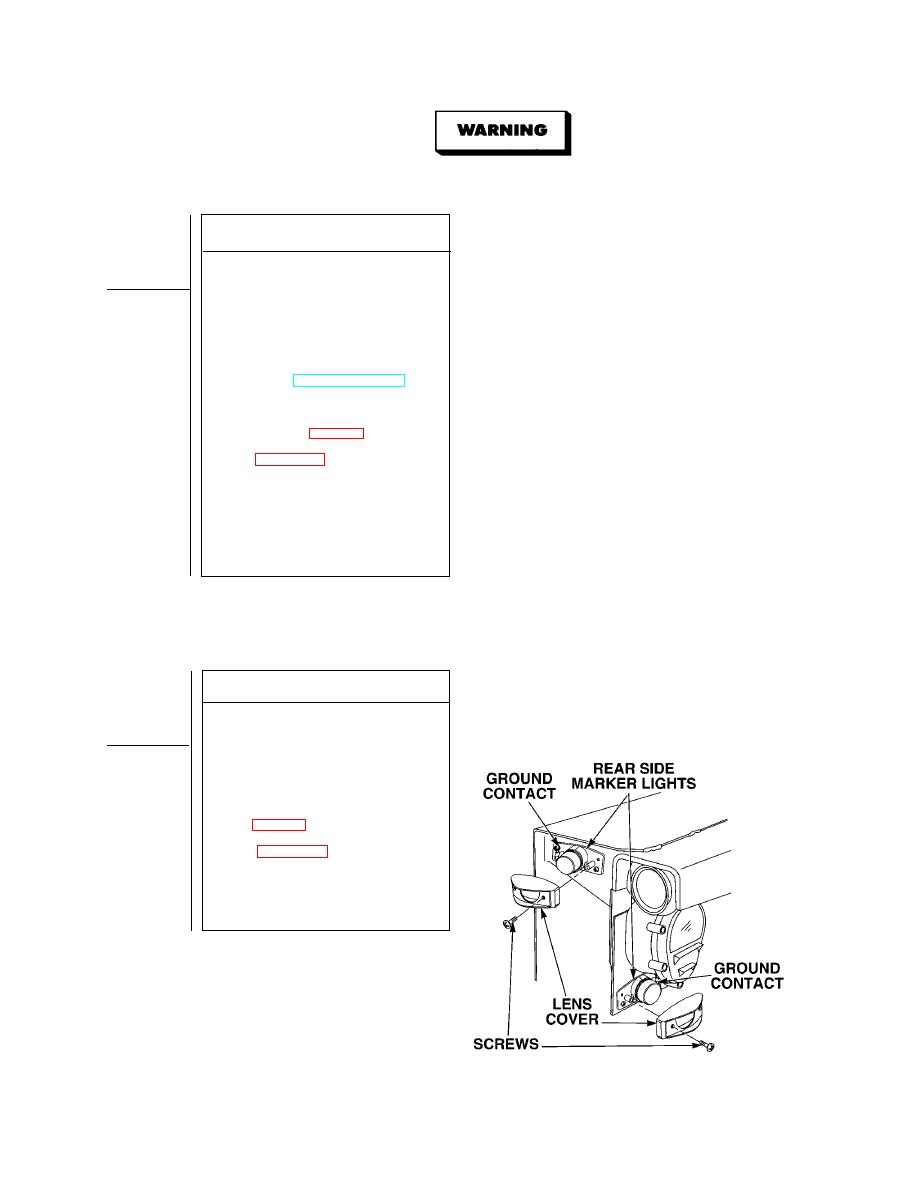
CONTINUITY TEST
(1) Remove two screws and lens cover.
(2) Set multimeter select switch to ohms.
(3) Is there continuity between rear side
marker light ground contact and a
known good ground?
(a) If there is no continuity,
repair wire 1435 (see schematic,
marker light wire harness
(b) If there is continuity, replace rear
side marker light assembly (Para
4-27.1).
(4) Install lens cover and two screws.
4-118.11
|
|
Privacy Statement - Press Release - Copyright Information. - Contact Us |
