 |
|||
|
|
|||
|
Page Title:
TAILLIGHT(S) DO NOT OPERATE. (Cont) |
|
||
| ||||||||||
|
|
 TM 9-2330-385-14
Remove all jewelry such as rings, dog tags, bracelets, etc. If jewelry or tools contact positive electrical circuits,
a direct short may result. Damage to equipment, injury, or death to personnel may occur.
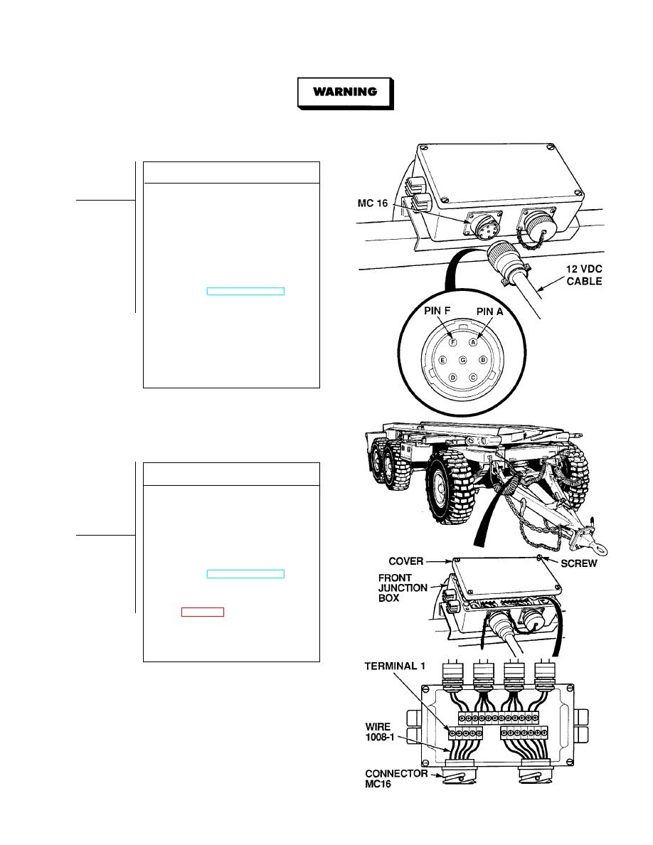
VOLTAGE TEST
(1) Disconnect 12 vdc (7 pin) cable from
front junction box connector MC16.
(2) Set multimeter select switch to
volts dc.
(3) Connect positive (+) multimeter lead
to pin F on trailer end connector.
(4) Connect negative (- ) multimeter lead
-
to terminal A on trailer end connector.
(5) While assistant turns ON ENGINE
switch and turns on lights, observe
multimeter (TM 9-2320-364-10).
(a) If 10 to 14 vdc are not present,
perform Steps (6) and (7) below,
and replace 12 vdc cable.
(b) If 10 to 14 vdc are present, 12 vdc
cable is OK.
(6) Turn off lights.
(7) Turn OFF ENGINE switch.
(8) Connect 12 vdc cable to front junction
box connector MC16.
VOLTAGE TEST
(1) Loosen four captive screws and
remove front junction box cover.
(2) Connect positive (+) multimeter lead
to front junction box, terminal 1.
(3) Connect negative (- ) multimeter lead
-
to a known good ground.
(4) While assistant turns ON ENGINE
switch and turns on lights, observe
multimeter (TM 9-2320-364-10).
(a) If 10 to 14 vdc are not present,
perform Steps (5) and (6) below,
and replace connector MC16
(b) If 10 to 14 vdc are present,
connector MC16 is OK.
(5) Turn off lights.
(6) Turn OFF ENGINE switch.
|
|
Privacy Statement - Press Release - Copyright Information. - Contact Us |
