 |
|||
|
|
|||
|
Page Title:
TAILLIGHT(S) DO NOT OPERATE. (Cont) |
|
||
| ||||||||||
|
|
 TM 9-2330-385-14
Remove all jewelry such as rings, dog tags, bracelets, etc. If jewelry or tools contact positive electrical
circuits, a direct short may result. Damage to equipment, injury, or death to personnel may occur.
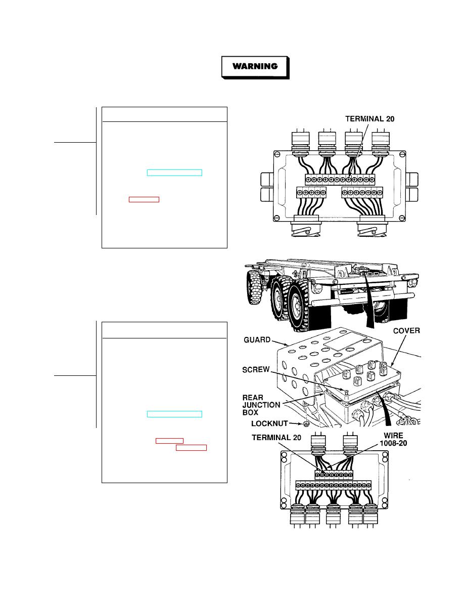
VOLTAGE TEST
(1) Connect positive (+) multimeter lead
to front junction box, terminal 20.
(2) Connect negative (- ) multimeter lead
-
to a known good ground.
(3) While assistant turns ON ENGINE
switch and turns on lights, observe
multimeter (TM 9-2320-364-10).
(a) If 10 to 14 vdc are not present,
perform Steps (4) and (5) below,
and replace front junction box
(b) If 10 to 14 vdc are present, front
junction box is OK.
(4) Turn off lights.
(5) Turn OFF ENGINE switch.
(6) Install front junction box cover
and tighten four captive screws.
VOLTAGE TEST
(1) Remove four locknuts and junction
box guard. Discard locknuts.
(2) Loosen four captive screws and
remove rear junction box cover.
(3) Connect positive (+) multimeter lead
to rear junction box, terminal 20.
(4) Connect negative (- ) multimeter lead
-
to a known good ground.
(5) While assistant turns on ON ENGINE
switch and turns on lights, observe
multimeter (TM 9-2320-364-10).
(a) If 10 to 14 vdc are not present,
perform Steps (6) and (7) below,
and repair wire 1008-20 (see
schematic, Fig FO-1) or replace
side wire harness (Para 4-30).
(b) If 10 to 14 vdc are present,
wire 1008-20 is OK.
(6) Turn off lights.
(7) Turn OFF ENGINE switch.
|
|
Privacy Statement - Press Release - Copyright Information. - Contact Us |
