 |
|||
|
|
|||
|
Page Title:
STOPLIGHT(S) DO NOT OPERATE. (Cont) |
|
||
| ||||||||||
|
|
 TM 9-2330-385-14
Remove all jewelry such as rings, dog tags, bracelets, etc. If jewelry or tools contact positive electrical
circuits, a direct short may result. Damage to equipment, injury, or death to personnel may occur.
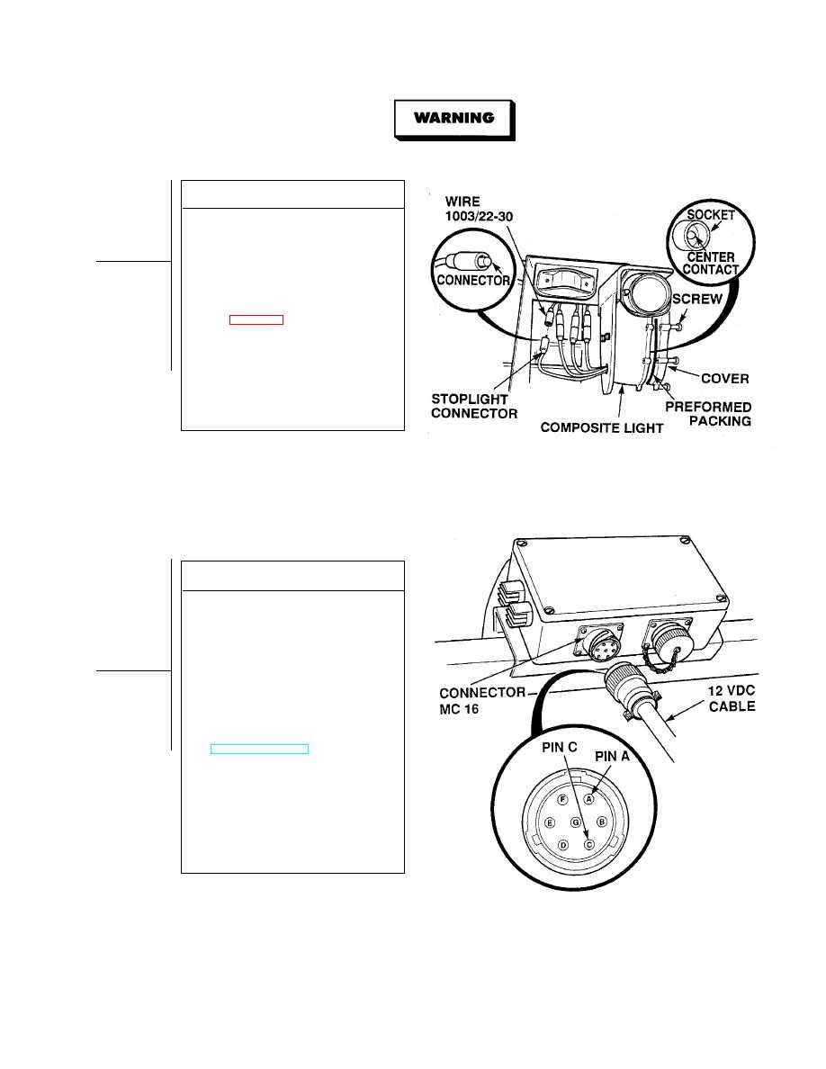
CONTINUITY TEST
(1) Disconnect wire 1003/22-30 at
stoplight connector.
(2) Set multimeter select switch to ohms.
(3) Is continuity measured between center
contact of stoplight socket
and connector?
(a) If there is no continuity,
replace composite light
(b) If there is continuity, composite
light is OK.
(4) Connect wire 1003/22-30 to
connector.
(5) Install lamp in stoplight socket.
(6) Install preformed packing and
composite light cover, and tighten six
captive screws.
VOLTAGE TEST
(1) Disconnect 12 vdc (7 pin) cable from
front junction box connector MC16.
(2) Set multimeter select switch to
volts dc.
(3) Connect positive (+) multimeter lead
to pin C on trailer end connector.
(4) Connect negative (- ) multimeter lead
-
to pin A on trailer end of
connector.
(5) While assistant turns ON ENGINE
switch and fully applies brake pedal,
observe multimeter
(TM 9-2320-364-10).
(a) If 10 to 14 vdc are not present,
perform Steps (6) and (7) below,
and replace 12 vdc cable.
(b) If 10 to 12 vdc are present, 12 vdc
cable assembly is OK.
(6) Release brake pedal.
(7) Turn OFF ENGINE switch.
(8) Connect 12 vdc cable to front junction
box connector MC16.
|
|
Privacy Statement - Press Release - Copyright Information. - Contact Us |
