 |
|||
|
|
|||
|
Page Title:
STOPLIGHT(S) DO NOT OPERATE. (Cont) |
|
||
| ||||||||||
|
|
 TM 9-2330-385-14
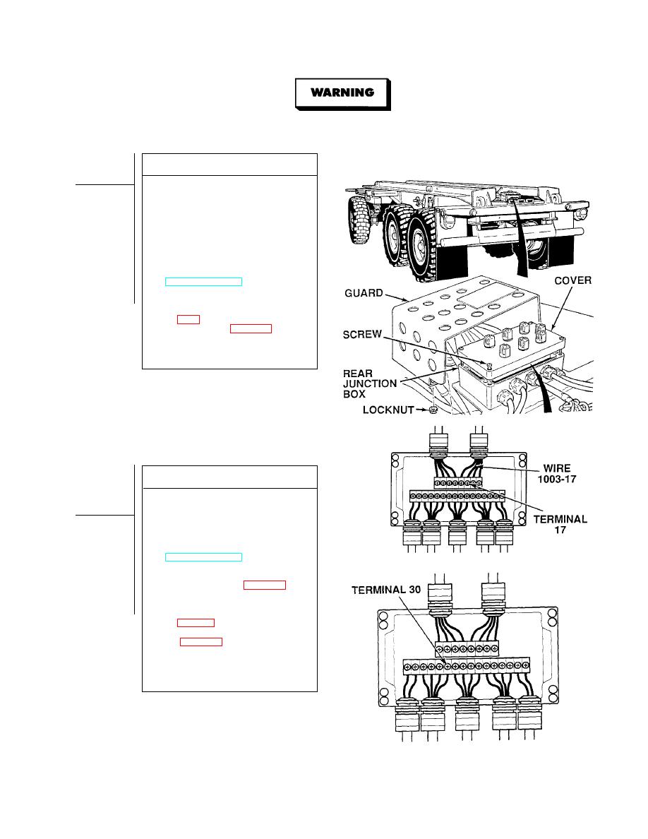
Remove all jewelry such as rings, dog tags, bracelets, etc. If jewelry or tools contact positive electrical
circuits, a direct short may result. Damage to equipment, injury, or death to personnel may occur.
VOLTAGE TEST
(1) Remove four locknuts and junction
box guard. Discard locknuts.
(2) Loosen four captive screws and
remove rear junction box cover.
(3) Connect positive (+) multimeter lead
to rear junction box, terminal 17.
(4) Connect negative (- ) multimeter lead
-
to a known good ground.
(5) While assistant fully applies brake
pedal, observe multimeter
(TM 9-2320-364-10).
(a) If 10 to 14 vdc are not present,
release brake pedal and repair
wire 1003-17 (see schematic, Fig
light harness (Para 4-30).
(b) If 10 to 14 vdc are present,
wire 1003-17 is OK.
(6) Release brake pedal.
VOLTAGE TEST
(1) Connect positive (+) multimeter lead
to rear junction box, terminal 30.
(2) Connect negative (- ) multimeter lead
-
to a known good ground.
(3) While assistant fully applies brake
pedal, observe multimeter
(TM 9-2320-364-10).
(a) If 10 to 14 vdc are not present,
release brake pedal, and replace
rear junction box (Para 4-26).
(b) If 10 to 14 vdc are present,
release brake pedal, and repair
wire 1003/22-30 (see schematic,
composite light harness
(4) Install rear junction box cover and
tighten four captive screws.
(5) Install junction box guard and four
locknuts.
|
|
Privacy Statement - Press Release - Copyright Information. - Contact Us |
