 |
|||
|
|
|||
|
Page Title:
Table 4-7. Parking Brake Air Lines |
|
||
| ||||||||||
|
|
 TM 9-2330-385-14
Axle No. 2
Axle No. 3
Axle No. 1
Air Hose No.
Air Hose No.
Air Hose No.
LH 2141
LH 2023
LH 2142
RH 2140
RH 2022
LH 2139
RH 2143
RH 2138
The LH and RH listed with the air hose numbers indicate the brake
chamber supplied by the listed air hose.
NOTE
Trailer air system pressure must be 125
S
5 psi (862 34 kPa) to begin
troubleshooting the brake system. If the
air system pressure cannot be maintained,
refer to Air System Troubleshooting.
Air lines and valves listed in this
S
troubleshooting procedure are illustrated
and located in FO-2.
VISUAL INSPECTION
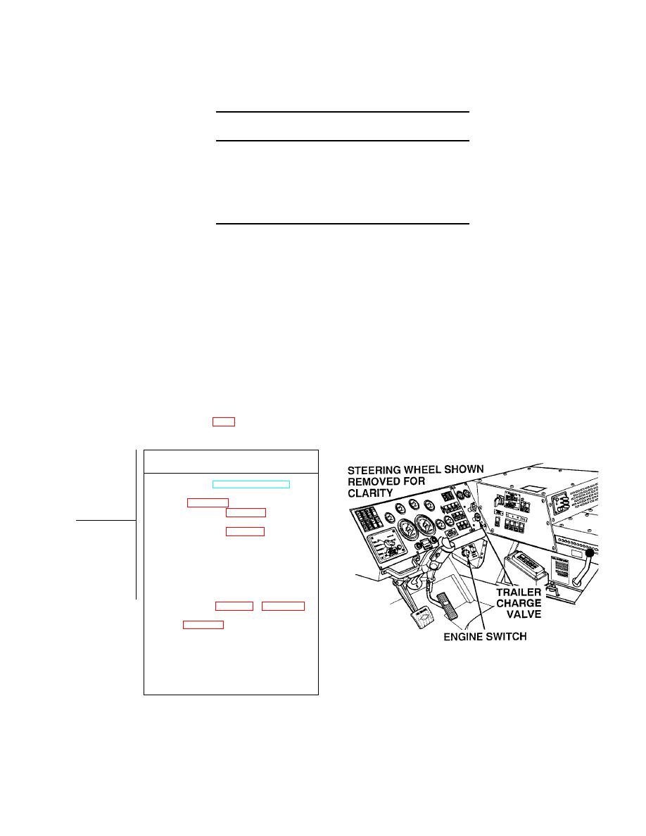
(1) Start engine (TM 9-2320-364-10).
(2) Push in trailer charge valve in
truck (Para 2-22).
(3) Inspect air lines (Table 4-7)
for crimps.
(4) Inspect air lines (Table 4-7), fittings,
and brake chambers for leaks.
(a) If fittings leak and are loose,
tighten fittings.
(b) If air hose(s) and/or brake
chamber(s) leak, perform
Steps (5) and (6) below and repair
or replace air lines (see
schematic Fig FO-2 or Para 4-47)
and/or replace brake chamber(s)
(c) If fittings, air lines, and brake
chambers do not leak, perform
Steps (5) and (6) below and go to
Step (2) of this Fault.
(5) Pull out trailer charge valve in truck.
(6) Turn OFF ENGINE switch.
4-257
|
|
Privacy Statement - Press Release - Copyright Information. - Contact Us |
