 |
|||
|
|
|||
|
|
|||
| ||||||||||
|
|
 TM 9-2330-385-14
This task covers:
a. Resistor/Circuit Board Test
c. Circuit Board Replacement
b. Resistor Replacement
d. Follow-On Maintenance
INITIAL SETUP
Tools and Special Tools
Material/Parts - Continued
Tool Kit, General Mechanic's
Heat Shrink (Item 14, Appendix E)
(Item 49, Appendix J)
Sealing Compound (Item 19, Appendix E)
Gun, Heat (Item 16, Appendix J)
Tags, Identification (Item 23, Appendix E)
Multimeter, Digital (Item 28, Appendix J)
Lockwasher (4) (Item 50, Appendix I)
Pencil, Soldering, Electric (Item 30, Appendix J)
Equipment Condition
Front electrical box removed, (Para 4-25)
Material/Parts
12 volt and 24 volt connectors removed,
Adhesive (Item 2, Appendix E)
Adhesive Sealant (Item 4, Appendix E)
a.
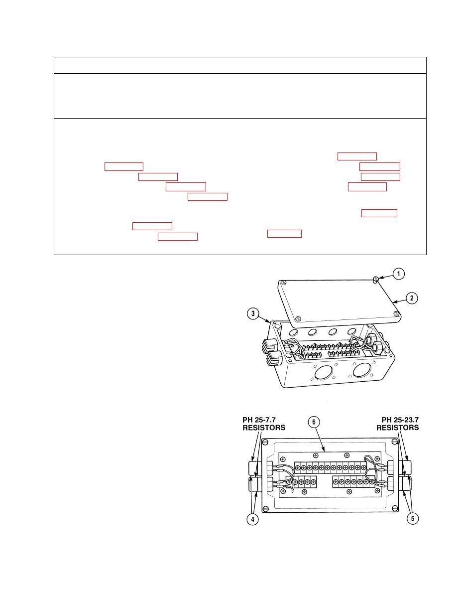
Resistor/Circuit Board Test.
(1)
Loosen four captive screws (1) and remove
box cover (2) from box (3).
(2)
Set multimeter select switch to ohms.
NOTE
Observe multimeter reading for a
measurement of 7.7 ohms 0.077
ohms. If measurement is
incorrect, replace resistor.
(3)
Connect positive multimeter lead to either
terminal of resistor (4).
(4)
Connect negative multimeter lead to
opposite terminal of resistor (4).
NOTE
Observe multimeter reading for a
measurement of 23.7 ohms
0.237 ohms. If measurement is
incorrect, replace resistor. If
measurement is correct, replace
circuit board.
(5)
Connect positive multimeter lead to either
terminal of resistor (5).
(6)
Connect negative multimeter lead
to opposite terminal of resistor (5).
|
|
Privacy Statement - Press Release - Copyright Information. - Contact Us |
