 |
|||
|
|
|||
|
Page Title:
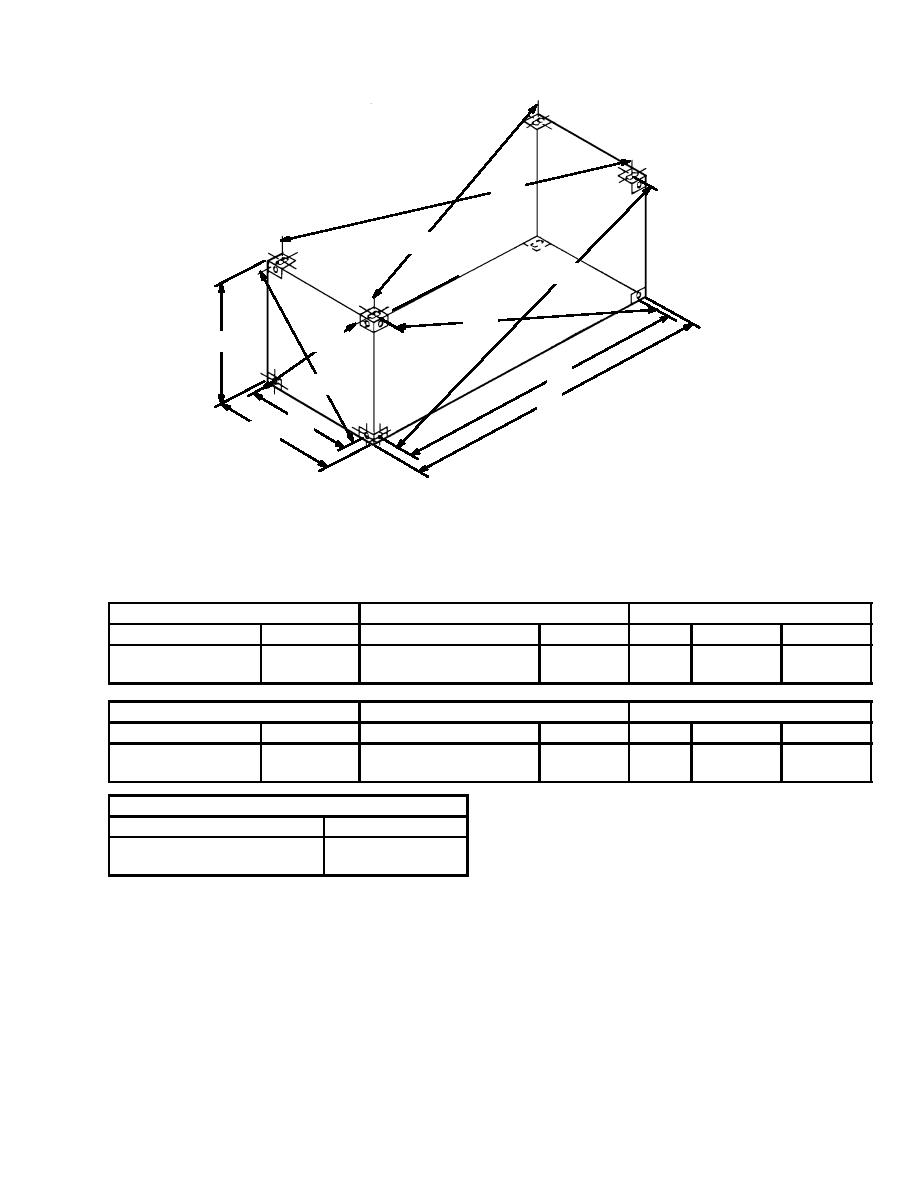
Figure 9-3. Configuration Measuring Points. |
|
||
| ||||||||||
|
|
 TM 9-3990-206-14&P
D2
D1
D3
D4
D6
H
S
D5
L
P
W
L (EXTERNAL LENGTH)
S
K1 MAX.
FT
IN
MM
FT
IN
MM
FT
IN
MM
19
10-1/2 +0
6.058 +0
19
2- 7/16 +3/16
5, 853 +5
13
1/2
3,975
- 1/4
-6
- 3/16
-5
W (EXTERNAL WIDTH)
P
K2 MAX.
FT
IN
MM
FT
IN
MM
FT
IN
MM
8
0
+0
2,438 +0
7
4-31/32 +5/32
2, 259 +4
10
3/8
3,058
- 3/16
-5
- 5/32
-4
H (OVERALL HEIGHT)
FT
IN
MM
6
0
+0
2,083 +0
- 3/16
-5
S
=
LENGTH BETWEEN CENTERS OF CORNER
FITTING APERATURES
P
=
WIDTH BETWEEN CENTERS OF CORNER
FITTING APERTURES
D=
DISTANCE BETWEEN CENTERS OF
APERTURES OF DIAGONALLY
OPPOSITE CORNER FITTINGS
K1 =
DIFFERENCE BETWEEN D1 AND D2
OR D3 AND D4
K2 =
DIFFERENCE BETWEEN D5 AND D6
9-9
|
|
Privacy Statement - Press Release - Copyright Information. - Contact Us |
