
TM 5-3990-263-13&P
FIELD MAINTENANCE
REFLECTOR REPLACEMENT
INITIAL SETUP:
References
Tools and Special Tools
Tool Kit, General Mechanics: Automotive
Parts Manual (WP 0073, Figure 10)
(WP 0078, Table 2, Item 2)
Equipment Condition
Materials/Parts
Load removed from the BAP. (WP 0008)
Lockwasher (WP 0082, Table 1, Item 41) Qty:
2
BAP unloaded from the CBT. (WP 0006)
REMOVAL
1.
Remove two screws (Figure 1, Item 1), nuts (Figure 1, Item 2), lockwashers (Figure 1, Item 3), and amber
reflector (Figure 1, Item 4) from A-frame (Figure 1, Item 5). Discard lockwashers.
1
5
4
3
2
Figure 1.
Front Amber Reflector Removal.
NOTE
Steps (2) through (4) are the same for removal of road-side and curb-side reflectors.
Engage pin lock assembly in manual position before removing or installing reflector.
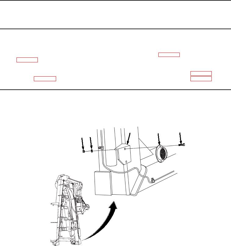
2.
Remove two screws (Figure 2, Item 6), lockwashers (Figure 2, Item 7), and amber reflector (Figure 2, Item 8)
from BAP frame (Figure 2, Item 9). Discard lockwashers.
03/15/2011Rel(1.8)root(maintwp)wpno(M04045)

