
TM 5-3990-263-13&P
0050
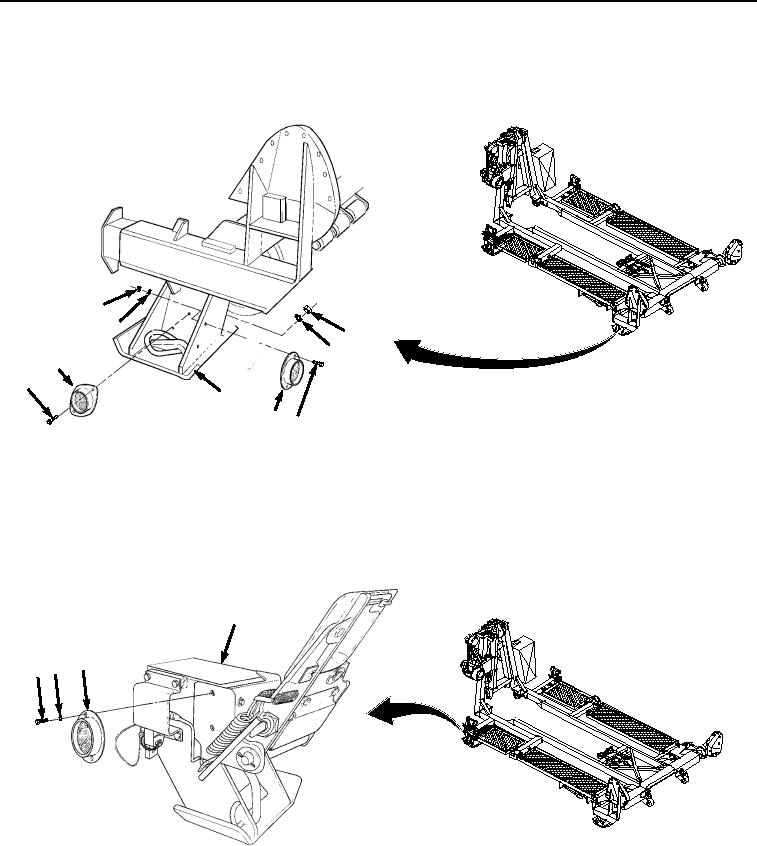
INSTALLATION - Continued
1.
Install red reflector (Figure 4, Item 17) on BAP frame (Figure 4, Item 9) with two screws (Figure 4, Item 14),
nuts (Figure 4, Item 15), and lockwashers (Figure 4, Item 16).
15
16
11
12
13
10
9
17 14
Figure 4.
Red Reflector Installation.
2.
Install red reflector (Figure 4, Item 13) on BAP frame (Figure 4, Item 9) with two screws (Figure 4, Item 10),
nuts (Figure 4, Item 11), and lockwashers (Figure 4, Item 12).
3.
Install amber reflector (Figure 5, Item 8) on BAP frame (Figure 5, Item 9) with two screws (Figure 5, Item 6)
and lockwashers (Figure 5, Item 7).
9
8
67
Figure 5.
Left Front Amber Reflector Installation.
4.
Install amber reflector (Figure 6, Item 4) on A-frame (Figure 6, Item 5) with two screws (Figure 6, Item 1), nuts
(Figure 6, Item 2), and lockwashers (Figure 6, Item 3).
03/15/2011Rel(1.8)root(maintwp)wpno(M04045)