|
| |
TM 9-2320-364-34-3
14-36
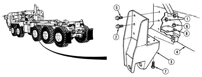
14-7. AXLE NO. 3 AIR SUSPENSION BEAM MOUNT REPLACEMENT/
ADJUSTMENT (CONT).
b.
Installation.
Trailing beam bracket weighs 83 lbs. (38 kg). Attach a suitable lifting device prior to
installation to prevent possible injury to personnel.
(1)
Support trailing beam bracket (3) with a lifting device.
(2)
Using a lifting device and the aid of an assistant, position trailing beam bracket (3) on frame (4).
(3)
Position plate (8), four screws (7) and locknuts (6) on frame (4) and trailing beam bracket (3).
NOTE
Steps (4) and (5) apply to right trailing beam mount only. Steps (6) and (7) apply to left trailing
beam mount only.
(4)
Position screw (5) and locknut (1) in trailing beam bracket (3) and frame (4).
(5)
Position three screws (2) and locknuts (1) in trailing beam bracket (3) and frame (4).
(6)
Position two screws (5) and locknuts (1) in trailing beam bracket (3) and frame (4).
(7)
Position four screws (2) and locknuts (1) in trailing beam bracket (3) and frame (4).
(8)
With the aid of an assistant, tighten four locknuts (6) to 210 lb-ft (285 N.m).
(9)
With the aid of an assistant, tighten locknuts (1) to 410 lb-ft (556 N.m).
|