 |
|||
|
|
|||
|
Page Title:
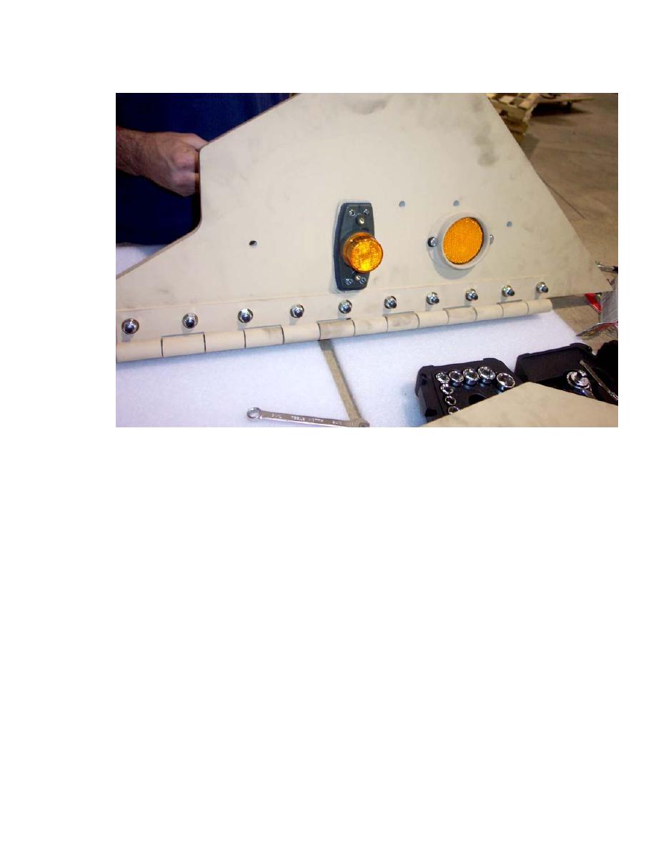
Figure 25. Install the amber clearance light and amber reflector onto the Front Side Cab Armor Panel. |
|
||
| ||||||||||
|
|
 II106700-5
Rev. B
Page 42
Front Side Cab Armor Panel.
h. Attach the amber reflector to the Front Side Cab Armor Panel using two internal hex
head bolts (1/4 - 20 x 0.500 LG) and two washers (1/4 ID).
k. Feed the amber clearance light wire through the Slit Grommet (P/N 111453-1) (If the
Grommet is not already slit, create the slit from the outer edge of the grommet into
the center hole.) and press the Grommet into the hole in the cab side, and secure the
Front Side Cab Armor Panels (P/Ns 111432-1 and 111432-3) to the cab using four
bolts (3/8 - 16 x 2.000 LG), four flat washers (3/8 ID), and four spacers
(P/N 113318-1) installed between the armor panels and the cab). Using a torque
wrench, tighten each of the four bolts to 20 ft-lb.
m. Connect the amber clearance light lead inside the cab using the Extension Pigtail
(P/N 111438-3).
n. Position the Front Side Cab Armor onto the side of the cab and secure the hinge to
the door pillar using 9 bolts (5/16 18 x 1.500 LG).
p. Secure the armor panel using four bolts (3/8 6 x 2.000 LG) into the previously
installed rivnuts.
r.
Repeat Steps "a" through "p" for the Side Armor Kit (LH), P/N 106703-9.
0039 00-52
|
|
Privacy Statement - Press Release - Copyright Information. - Contact Us |
