 |
|||
|
|
|||
|
Page Title:
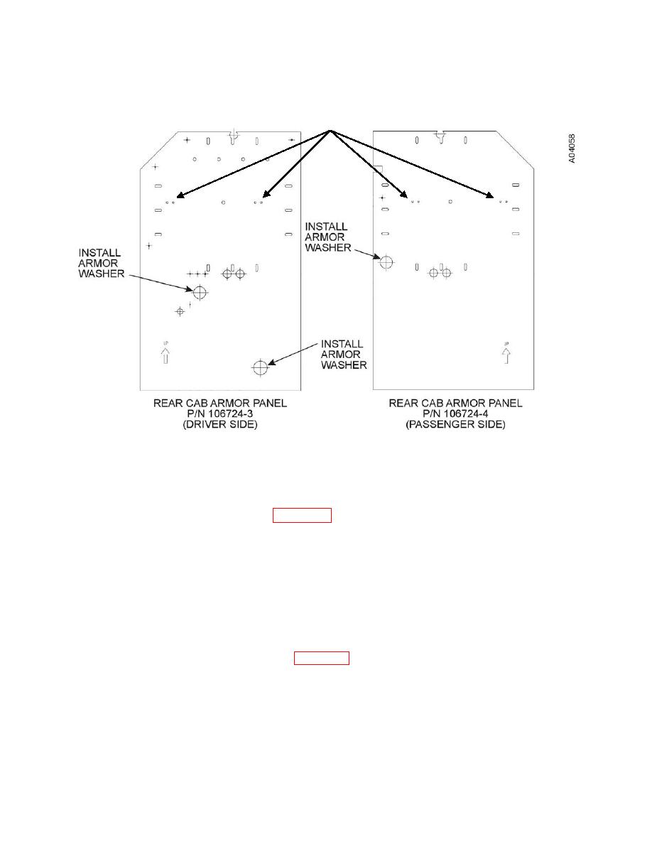
Figure 29a. Armored washer locations. |
|
||
| ||||||||||
|
|
 II106700-5
Rev. B
See Paragraph "p"
(used four times)
Figure 29a. Armored washer locations.
p. Prior to installation, insert four bolts (1/4 20 x 1.000), eight washers (1/4 ID), and
four nuts (1/4 -20) through the four optional energy-absorbing seat mounting holes
on each armor panel (see Figure 29a for locations). Ensure that the nut is on the
outboard side.
(Driver's-side) and P/N 106703-10 (Passenger-side)
a. Install a lift strap through the lifting eyes on top of the Armored Door Assembly
[P/N 111430-1 (Driver's-side) / 111430-2 (Passenger-side)].
b. Using the lift strap and material handling equipment (hoist, forklift, etc.), position the
Armored Door Assembly into the cab door opening and install the Armored Door
Assembly to the cab hinge (See Figure 32) using 10 bolts (3/8 16 x 1.500 LG),
20 washers (3/8 ID) and 10 locknuts (3/8 16). Hand-tighten the bolts to secure the
door to the cab for adjustment.
0039 00-61
|
|
Privacy Statement - Press Release - Copyright Information. - Contact Us |
