 |
|||
|
|
|||
|
|
|||
| ||||||||||
|
|
 II113300-1-103
Rev. A
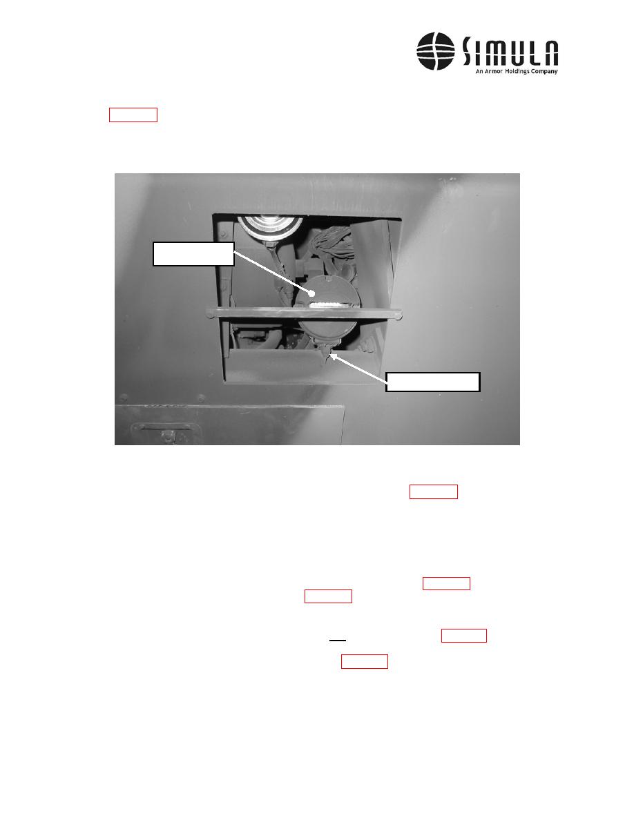
g) Remove the Blackout Light attached to a bracket located in front of the vehicle (see
connecter on the electrical wire that leads to the light. The connector is located
approximately 8 in. from the Blackout Light. Do not disconnect the wire were the wire
enters the light's housing.
Blackout Light
Remove this bolt
h) Remove both Headlights located in front of the vehicle (see Figure 5). This is done by
removing the three nuts that attach the Headlight to the cab. The nuts may be found
inside the vehicle just behind the light. On the passenger side, the lower section of the
glove box must be removed to access these nuts. Remove and mark the three wire
connectors on the back of each light so that the same connection locations may be used
when the lights are re-installed.
i)
Remove the five bolts around the face of the Marker Light (see Figure 8). If the inside of
the Marker Light looks like the one in Figure 8, mark and disconnect the connecting
wires from the inside of the vehicle. Remove the rubber boots on the end of the four
wires. Then, feed the wires out through the hole in the cab and remove the Marker
Light. If the inside of the marker light does not look like the one in Figure 8, it will be
necessary to also remove the Marker Light Housing. To access the attachment bolts on
the driver side, the Mounting Plate, shown in Figure 9, must be detached from the cab.
Four bolts are used to attach the Mounting Plate, two on top and two on the bottom. The
two on the top only need to be loosened. Once they are loose and the bottom two bolts
are removed, the Mounting Plate will slide downward and enable it to be moved out of
the way. It may be necessary to remove other wires. Mark and remove the wires as
necessary to access the bolts. Note: No instruction is provided later in this manual to
re-install wires that are not marked.
0037 00-32
|
|
Privacy Statement - Press Release - Copyright Information. - Contact Us |
