
TB 9-2320-364-13&P-2
HEADLIGHT AND COMPOSITE LIGHT REPLACEMENT - CONTINUED
0020 00
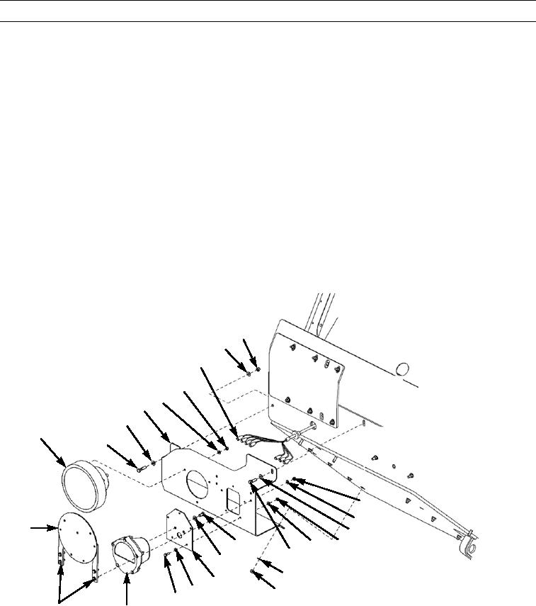
INSTALLATION (CONFIGURATION B)
N OT E
The following procedure covers both left and right headlight assemblies (Configuration B).
Right headlight assembly (Configuration B) is illustrated.
1.
Position headlight bracket (5) over mounting holes on lower brush guard.
2.
Install two washers (4), bolts (3), washers (9), and new locknuts (10) to top of headlight bracket (5).
3.
Install three washers (15) and new locknuts (16) to bottom of headlight bracket (5).
4.
On right side only, install weight classification marker (2) to headlight bracket (5) with four washers (17), bolts (18),
washers (12), and new locknuts (11).
5.
Install composite light (29) to headlight adapter (26) with two washers (25) and bolts (24).
6.
Install headlight adapter (26) with composite light (29) to headlight bracket (5) with five washers (27), bolts (28), wash-
ers (23), and new locknuts (22).
7.
Install headlight (1) to headlight bracket (5) with three washers (6) and new locknuts (7).
8.
Connect jumper harness connectors (8) to headlight (1) and composite light (29).
10
9
8
7
6
5
4
1
3
11
12
2
4
23
24
22
3
25
15
26
27
16
417-027
28
17,18
29
CONFIGURATION B
9.
Connect battery cables (TM 9-2320-364-20).
10.
Check operation of headlights and composite lights (TM 9-2320-364-10).
END OF WORK PACKAGE
0020 00-5/(0020 00-6 Blank)