
TM 5-3990-263-13&P
0011
OPERATION - Continued
NOTE
Ensure air release valve lever safety pin is engaged through release lever.
10.
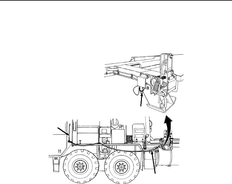
Attach lanyard (Figure 4, Item 15) to front bridge lock air release valve lever (Figure 4, Item 16).
16
17
15
Figure 4. Attach Lanyard to Air Release Valve.
11.
Run lanyard (Figure 4, Item 15) forward and attach to vehicle handgrip (Figure 4, Item 17).
12.
Remove air hose from stowage connector (Figure 5, Item 18) (road-side of the BAP) and connect to vehicle
tire inflation air connector (Figure 5, Item 19).
03/15/2011Rel(1.8)root(opusualwp)wpno(O01059)