TM 5-3990-263-13&P
0011
OPERATION - Continued
CAUTION
Ensure hook holder is stowed in saddle. Failure to comply may result in damage to hook.
18.
Release WINCH switch (Figure 9, Item 26) when hook holder (Figure 9, Item 27) is in saddle (Figure 19, Item
28).
19.
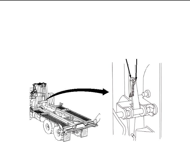
Secure winch frame to the BAP. Ensure two winch frame locking levers (Figure 10, Item 29) are in the up
position.
29
30
Figure 10.
Lock Winch Frame to BAP.
20.
If locking levers (Figure 10, Item 29) are not up:
a.
Remove lockpin (Figure 10, Item 30) from locking lever (Figure 10, Item 29).
b.
Swing locking lever (Figure 10, Item 29) to the up position.
c.
Insert lockpin (Figure 10, Item 30) into locking lever (Figure 10, Item 29).
NOTE
Interior bay has four foldlock latches and two travel latches. Ramp bay has two foldlock
latches and one travel latch.
21.
Release all bay foldlock latches (Figure 11, Item 31) and all travel latches (Figure 11, Item 32). Refer to TM
5-5420-278-10.
03/15/2011Rel(1.8)root(opusualwp)wpno(O01059)

