|
| |
TM 9-2320-364-20-3
2-2467
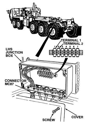
(1) Loosen four screws and open LHS
junction box.
(2) Set multimeter selector switch
to volts dc.
(3) Connect positive (+) multimeter lead
to LHS junction box, terminal 1.
(4) Connect negative (–) multimeter lead
to a known good ground.
(5) Turn ON ENGINE switch
(TM 9-2320-364-10).
(a) If there are not 22 to 28 vdc
present, perform Step (6) below.
(b) If there are 22 to 28 vdc present,
wire 1461 is OK.
(6) Turn OFF ENGINE switch,
(TM 9-2320-364-10).
VOLTAGE TEST
Remove all jewelry such as rings, dog tags, bracelets, etc. If jewelry or tools contact positive electrical
circuits, a direct short may result. Damage to equipment, injury or death to personnel may occur.
(1) Disconnect wire 1435 (coming from
harness connector MC87) from
terminal 2.
(2) Set multimeter selector switch
to ohms.
(3) Is there continuity between harness
connector MC87, terminal 2 wire 1435
and a known good ground?
(a) If there is no continuity, repair wire
1435 (see schematic Fig 2-52) or
notify DS Maintenance.
(b) If there is continuity, wire 1435
is OK.
(4) Connect wire 1435 to terminal 2.
CONTINUITY TEST
|