|
| |
TM 9-2320-364-20-5
18-28
Materials/Parts
Adhesive, Retaining (Item 13, Appendix C)
Sealing Compound (Item 77, Appendix C)
This task covers:
a. Removal
b. Installation
c. Follow-On Maintenance
INITIAL SETUP
Equipment Condition
Engine OFF, (TM 9-2320-364-10)
Wheels chocked, (TM 9-2320-364-10)
Tools and Special Tools
Tool Kit, General Mechanic’s: Automotive
(Item 74, Appendix G)
Socket Set, 3/8 in. (Item 62, Appendix G)
Wrench, Torque (0-60 N.m)
(Item 98, Appendix G)
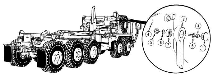
18-7. CRANE ANGLE INDICATOR REPLACEMENT.
a.
Removal.
NOTE
Both angle indicators are removed the same way.
(1)
Remove cap plug (1) from pointer (2).
(2)
Remove screw (3) and pointer (2) from crane frame (4).
(3)
Remove nut (5), two washers (6) and screw (3) from bearing (7).
NOTE
Perform Step (4) if bearing is damaged.
(4)
Remove bearing (7) from pointer (2).
|