|
| |
TM 9-2320-364-34-2
6-221
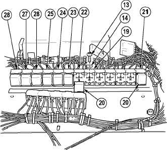
NOTE
Refer to Figure 6-1 for relay
mounting positions.
(35)
Install relay sockets R24 (28), R17 (19) and
R12 (21) with three lockwashers (14) and
screws (13).
(36)
Install eight 24V relays (20) in relay
sockets R12 (21), R18 (22), R19 (23), R20
(24), R21 (25), R22 (26), R23 (27) and
R24 (28).
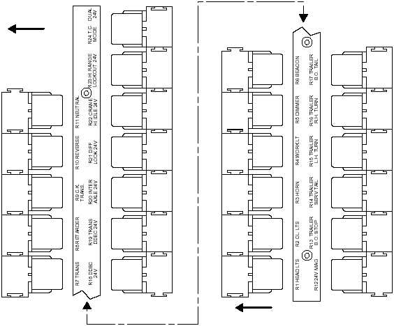
Figure 6-1. Relay Mounting Positions
R11
12V
R10
12V
R9
12V
R8
12V
R7
12V
R24
24V
R23
24V
R22
24V
R21
24V
R20
24V
R19
24V
R18
24V
R6
12V
R5
12V
R4
12V
R3
12V
R2
12V
R1
12V
R17
12V
R16
12V
R15
12V
R14
12V
R13
12V
R12
24V
RIGHT FRONT
LEFT FRONT
|