|
| |
TM 9-2320-364-34-2
9-39
a.
Removal.
The following Step keeps clutch
gear from disengaging after
constant velocity shafts are
removed. Failure to perform
Step makes assembly difficult
and could damage parts.
NOTE
The screw used in Step (1)
is from locking cylinder.
Step (1) is for right side
constant velocity shaft
removal on Axles No. 1 and
5 only.
Step (1) is for left side
constant velocity shaft
removal on Axle No. 2 only.
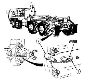
Axles No. 1, 2 and 5
constant velocity shafts are
removed the same. Axle
No. 5 is shown.
(1)
Position a wire around fingers of fork (1)
and anchor wire with screw (2).
|