|
| |
TM 9-2320-364-34-4
20-302
Materials/Parts
Oil, Diesel Fuel (Item 32, Appendix B)
Oil, Lubricating (Item 36, Appendix B)
Gasket (Item 93, Appendix E)
Packing, Preformed (2) (Item 380, Appendix E)
This task covers:
a. Installation
b. Follow-On Maintenance
INITIAL SETUP
Equipment Condition
Timing and Synchronous Reference Sensor
installed, (Para 20-91)
Tools and Special Tools
Tool Kit, General Mechanic’s
(Item 240, Appendix F)
Wrench, Fuel Line (Item 270, Appendix F)
Wrench Set, Socket 3/8 in. Drive
(Item 273, Appendix F)
Wrench, Torque (0-60 N.m)
(Item 276, Appendix F)
Wrench, Torque (0 to 175 lb-ft [0-237 N.m])
(Item 277, Appendix F)
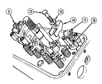
20-92. FUEL INJECTOR INSTALLATION.
a.
Installation.
NOTE
There are eight fuel injectors. All fuel injectors are installed the same way. Right side
shown.
Fill injectors with diesel fuel prior to installation.
(1)
Insert injector (5) into injector tube hole (15).
Do not force rocker arms all the
way back with shaft in place.
Failure to comply could result
in damage to push rods.
Ensure clamp does not interfere
with injector spring or valve
springs. Interference of clamp
with spring travel can cause
damage to components.
NOTE
Curved side of washer is installed
facing clamp.
(2)
Lift rocker arms (11) and install clamp (14),
washer (13) and screw (12). Tighten screw
20 to 25 lb-ft (27 to 34 N.m).
|