|
| |
TM 9-2320-364-34-4
20-358
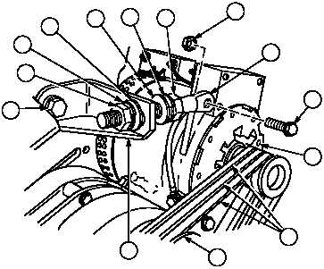
20-106. REMOVING ENGINE FROM STAND (CONT).
(31)
Position three alternator belts (90) on
alternator (86) and engine pulley (91).
(32)
Install nut (80), lockwasher (88) and washer
(87) on alternator arm (81).
(33)
Position alternator support arm (81) in
bracket (89).
(34)
Tighten screw (109) to 170 lb-ft (23 N.m).
(35)
Position alternator support arm (81) on
alternator (86) with screw (85) and locknut
(84).
(36)
Position washer (83), lockwasher (82) and
nut (79) on alternator support arm (81).
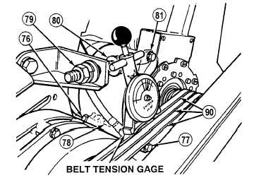
(37)
Install belt tensioning gage on belts (90).
(38)
Tighten locknut (80) on alternator support
arm (81) until alternator belts tension reaches
60 to 65 lb-ft (81-88 N.m).
(39)
Tighten locknut (79) on alternator support
arm (81).
(40)
Remove belt tensioning gage from belts (90).
(41)
Tighten locknut (84) on screw (85) to
26-30 lb-ft (30-41 N.m).
(42)
Tighten locknut (76) on screw (77) and
alternator mounting bracket (78) to 90 lb-ft
(122 N.m).
81
85
84
86
89
82
91
79
83
90
87
88
80
109
|