|
| |
TM 9-2320-364-34-4
24-46
24-8. TRANSFER CASE ASSEMBLY REPAIR (CONT).
NOTE
Ensure shaft assembly is fully
seated prior to performing
Step (121).
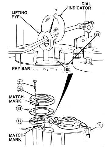
(121)
Install lifting eye in end of center shaft
assembly (45).
(122)
Position dial indicator and measure end play
on center shaft assembly (45).
(123)
While using pry bar to lift center shaft
assembly (45) as far as possible, record
deflection on dial indicator.
NOTE
If deflection is less than 0.003 in.
(0.076 mm), shims (28) must be
added. If deflection is more than
0.006 in. (0.152 mm), shims must
be removed.
(124)
If end play deflection is 0.003 to 0.006 in.
(0.076 to 0.152 mm). Go to Step (134).
(125)
Matchmark steering pump adapter
plate (26) and rear housing (4).
(126)
Remove six screws (27) and adapter
plate (26) from rear housing (4).
(127)
Remove shims (28) from rear housing (4).
(128)
Add or remove shims (28) to stack to equal
proper thickness.
|