 |
|||
|
|
|||
|
Page Title:
SPRING REPLACEMENT (AXLE NO.1). |
|
||
| ||||||||||
|
|
 TM 9-2330-385-14
This task covers:
a. Removal
b. Installation
c. Follow-On Maintenance
INITIAL SETUP
Tools and Special Tools
Materials/Parts - Continued
Tool Kit, General Mechanic's
Bushing (2) (Item 3, Appendix I)
(Item 49, Appendix J)
Pin, Cotter (6) (Item 64, Appendix I)
Socket Set, 3/4 in. (Item 39, Appendix J)
Personnel Required
Wrench Set, Crowfoot (Item 58, Appendix J)
Two
(Item 61, Appendix J)
Equipment Condition
Lifting Device Minimum Capacity 270 lb (123 kg)
Wheels chocked, (Para 2-20)
Axle assembly removed, (Para 5-14)
Materials/Parts
Grease (Item 12, Appendix E)
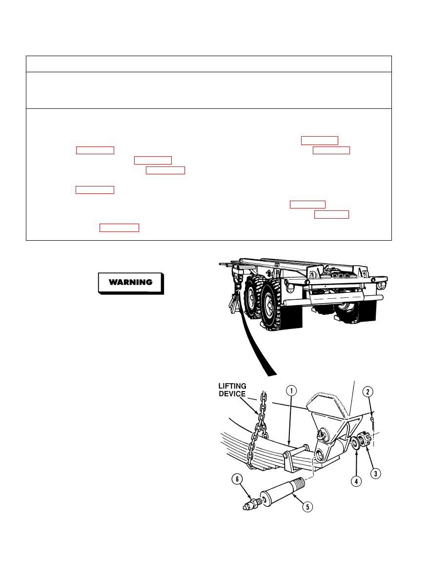
a.
Removal.
Spring weighs 163 lbs
(74 kg). Attach suitable
lifting device prior to
removal to prevent possible
injury to personnel.
Keep hands and fingers out
of spring pin hole or injury
to personnel may result.
(1)
With the aid of an assistant, attach lifting
device to spring (1).
(2)
Remove two cotter pins (2), castle nuts (3),
washers (4) and spring pins (5) from both
ends of spring assembly. Discard cotter pins.
(3)
Lower spring (1).
(4)
Remove lifting device from spring (1).
NOTE
Perform Step (5) if grease
fittings are damaged.
(5)
Remove grease fittings (6) from spring
pins (5). Discard grease fittings.
|
|
Privacy Statement - Press Release - Copyright Information. - Contact Us |
