 |
|||
|
|
|||
|
|
|||
| ||||||||||
|
|
 TM 9-3990-206-14&P
10-7. WALL REPLACEMENT (CONT).
21
22
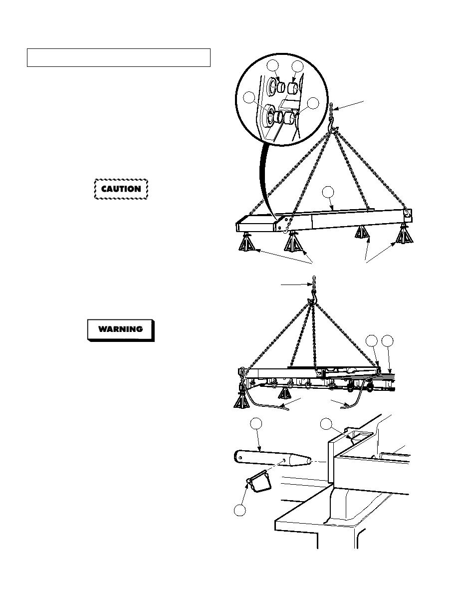
NOTE
Note position of bushings prior to
removal.
LIFTING
23
20
All four sets of bushings are
DEVICE
removed the same way. Left front
set is shown.
(20)
Remove and discard four bushings (20),
(21), (22) and (23) from wall (2).
(21)
Repeat Step (20) for other side of wall (2).
b.
Installation.
2
Ensure bushings do not protrude
outer edges of bore when
installed. Failure to comply may
result in damage to equipment.
NOTE
All four sets of bushings are
JACKSTANDS
installed the same way. Left front
set is shown.
LIFTING
(1)
Install four bushings (23), (22), (21) and
DEVICE
(20) in wall (2).
(2)
Repeat Step (1) for other side of wall (2).
2
19
Front wall weighs 1,500 lbs (681 kg).
Rear wall weighs 1,200 (545 kg). Attach
suitable lifting device prior to lifting wall
to prevent injury or death to personnel.
LADEN LIFT
EMPTY LIFT
EMPTY LIFT
F POCKET
F POCKET
(3)
With the aid of an assistant and using lifting
F POCKET
GUIDE
device and guide rope, position wall (2) on
ROPE
deck (19).
NOTE
17
18
Perform Steps (4), (5) and (6) for
front wall only.
Wall is properly positioned on
deck when hinge pin holes are
aligned.
Right and left pins are installed
the same way. Left side shown.
(4)
Install pin (17) in hinge (18).
16
(5)
Install two safety pins (16) in pin (17).
(6)
Repeat Steps (4) and (5) for other side of
wall.
10-10
|
|
Privacy Statement - Press Release - Copyright Information. - Contact Us |
