
II113300-1-103
Rev. A
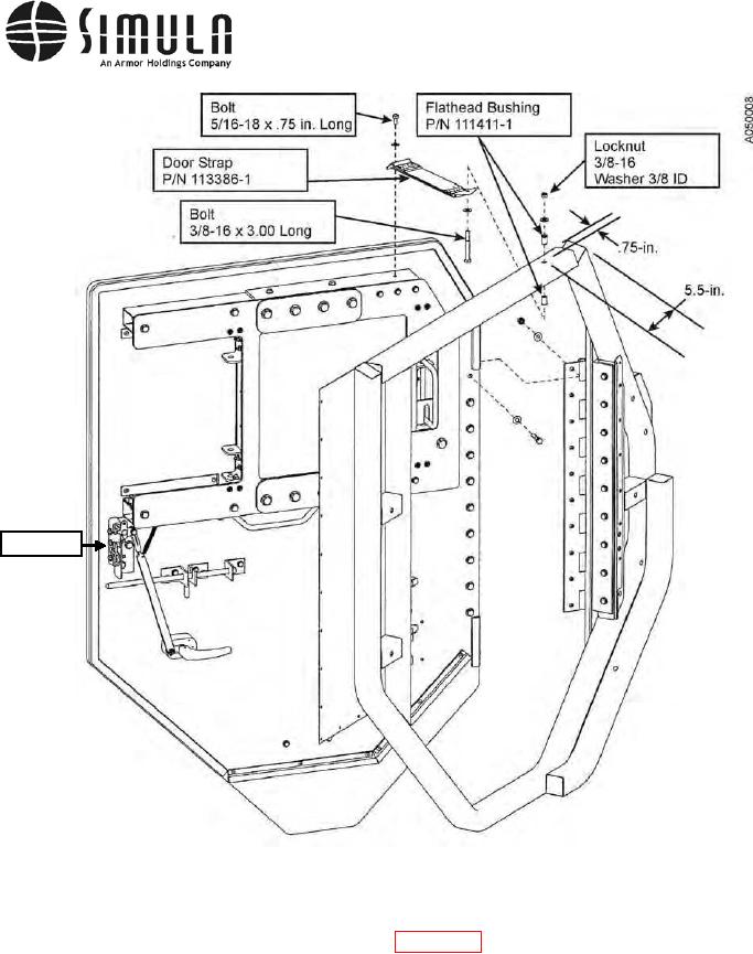
Door Latch
Figure 29. Armored Door and Door Strap.
bb) Re-position the Door Latch Assembly (see Figure 29) if required, by loosening its
attachment hardware so that the door smoothly engages the Door Striker Pin and then
tighten the attachment hardware.
NOTE
If necessary, washers or shims may be placed between the door latch assembly and the
door to adjust the latch inward if the latch is not completely engaging the striker. The shim
adjustment should not exceed 3/16 in.
0037 00-57