
TM 5-3990-263-13&P
0004
Table 1.
Load Handling System (LHS) Cab Controls and Indicators - Continued
Key
Control/Indicator
Function
4
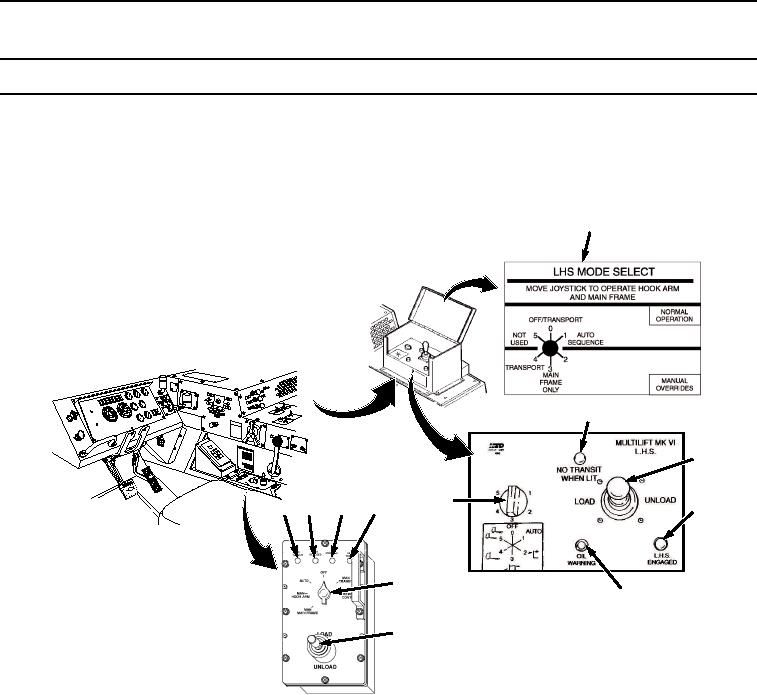
LHS MODE
Identifies functions of numbered positions of LHS MODE SELECT switch.
SELECT Switch
Position Decal
(Analog Only)
4
JACO
BS
ENGIN
E
BRAK
E
6
CAUT
ION
XHA
OE U
ILER Y
TRA PILG
RSUPND
N
ANIOTFORDPARK
ILA
M
US
HTO
7
5
8
6
8
10
9
5
9
ANALOG CBT
7
CONTROL PANEL
DIGITAL CBT
CONTROL PANEL
Figure 2. Analog and Digital Control Panels.
5
LHS MODE
Used to select functional modes for LHS. Positions and functions are:
SELECT SWITCH
OFF/TRANSPORT LHS is not operational.
AUTO SEQUENCE Provides automatic operation of LHS during loading and
unloading operations.
HOOK ARM ONLY Places hook arm in manual mode for moving hook arm
when AUTO mode electric circuit is malfunctioning.
MAIN FRAME ONLY Places main frame in manual mode for moving main
frame when AUTO mode electric circuit is malfunctioning.
TRANSPORT Provides for safe travel when AUTO mode electric circuit has
failed and HOOK ARM ONLY and MAIN FRAME ONLY positions have been
used.
03/15/2011Rel(1.8)root(ctrlindwp)wpno(O01003)