
TM 5-3990-263-13&P
0004
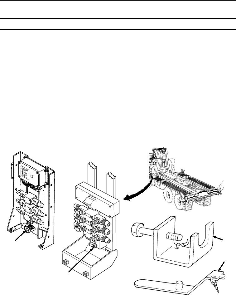
Table 1.
Load Handling System (LHS) Cab Controls and Indicators - Continued
Key
Control/Indicator
Function
17
Hourmeter (Analog
Records number of hours hydraulic unit is in operation.
only)
17
Electronic Control
Receives electronic signals from cab controls to operate solenoids.
Module (Digital only)
18
Main Frame
Raises main frame during emergency operations when electric power is lost.
19
Hook Arm Solenoid
Raises hook arm during emergency operations when electric power is lost.
20
Winch Solenoid
Pays out winch cable during emergency operations when electric power is lost.
21
Main Relief
Is main hydraulic relief valve.
23
22
DIGITAL
24
22
ANALOG
Free-Flow Valve.
Figure 5.
03/15/2011Rel(1.8)root(ctrlindwp)wpno(O01003)