DRAFT
TB 9-2320-364-13&P-1
AC DOES NOT COOL OR COOLS INADEQUATELY - Continued
WARNING
Remove rings, bracelets, wristwatches, neck chains, and any other jewelry before working around
vehicle. Jewelry can catch on equipment and cause serious injury. Jewelry or tools may short
across electrical circuits or terminals and cause damage to equipment or severe burns or
electrical shock to personnel.
Wear protective goggles and nonleather gloves when servicing air conditioner system. Failure to
comply may result in injury to personnel.
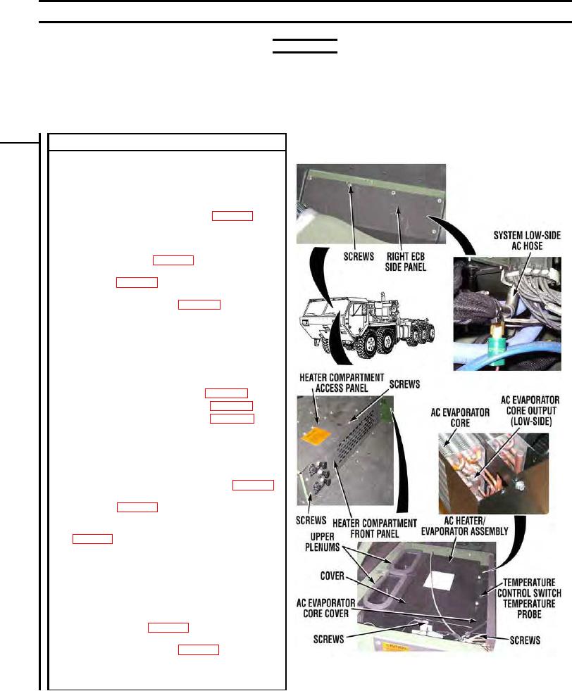
VISUAL INSPECTION
(1)
Shut off engine (TM 9-2320-364-10).
(2)
Remove eight screws and heater compartment access
panel (TM 9-2320-364-20).
(3)
Remove two upper plenums (TM 9-2320-364-20).
(4)
Remove four screws, lockwashers, washers, and cover
from AC heater/evaporator assembly (WP 0030).
CAUTION: Slide temperature probe slowly from evaporator
core. Failure to comply may result in damage to equipment.
(5)
Remove temperature control switch temperature probe
from evaporator core (WP 0044).
(6)
Remove four screws and pull heater compartment front
panel aside (WP 0037).
(7)
Remove four screws and evaporator core cover from AC
heater/evaporator assembly (WP 0030).
(8)
Remove ten screws and right ECB side panel
(TM 9-2320-364-20).
(9)
Inspect AC evaporator core and system low-side AC
hose at AC evaporator core for excessive sweating and
frost.
(a) If AC evaporator core and system low-side AC hose
are not free from excessive sweating and frost:
1. Recover R-134a refrigerant (WP 0053).
2. Replace AC expansion valve (WP 0030).
3. Replace AC condenser dryer (WP 0024).
4. Perform Steps 10 through 15 below.
(b) If AC evaporator core and system low-side AC hose
are free from excessive sweating and frost, perform
Steps 10 through 16 below.
(10) If removed, install evaporator core cover and four
screws on AC heater/evaporator assembly (WP 0030).
(11) If removed, install heater compartment front panel and
four screws (WP 0037).
(12) If removed, install cover and four washers, lockwashers,
and screws on AC heater/evaporator assembly
(13) Install two upper plenums (TM 9-2320-364-20).
CAUTION: Do not puncture temperature probe. Failure to
comply will cause gas to leak out.
NOTE: Slide temperature probe in evaporator core slowly.
Temperature probe must be slid into AC evaporator core until
it touches the bottom of insertion hole.
(14) Install temperature control switch temperature probe in
AC evaporator core (WP 0044).
(15) If expansion valve was replaced in Step 9 above,
evacuate and charge system (WP 0053). Verify repair,
go to Step 22 of this fault.
(16) If expansion valve was not replaced in Step 9 above, go
PLSAC210
to Step 13 of this fault.

