
TM 5-3990-263-13&P
0006
OPERATION - Continued
11.
Turn LHS MODE SELECT switch (Figure 8, Item 16) to AUTO.
18
19
17
JACO
BS
1
ENGIN
EBRA
KE
CAUT
ION
XHA
OE U
ILER Y
TRA PILG
RSUPND
N
ANIOTFORDPARK
ILA
M
US
HTO
20
16
2
16
ANALOG CBT
CONTROL PANEL
20
DIGITAL CBT
CONTROL PANEL
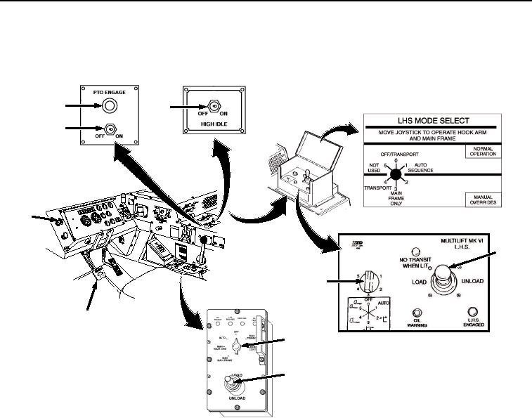
Figure 8.
Cab LHS Controls.
CAUTION
Do not position PTO ENGAGE switch to ON with HIGH IDLE switch ON. Engaging the
PTO with HIGH IDLE switch ON may result in sudden application of hydraulic pressure
to the LHS. Failure to comply may result in damage to equipment.
PTO ENGAGE switch must be positioned OFF before road transport. Failure to comply
may result in damage to equipment.
12.
Set PTO ENGAGE switch (Figure 8, Item 17) to ON position. Indicator light (Figure 8, Item 18) will illuminate.
13.
Set HIGH IDLE switch (Figure 8, Item 19) to ON position.
14.
Move joystick (Figure 8, Item 20) to UNLOAD and hold while LHS hook arm rises and moves the BAP to the
rear.
03/15/2011Rel(1.8)root(opusualwp)wpno(O01055)