
TM 5-3990-263-13&P
0007
OPERATION - Continued
11
9
10
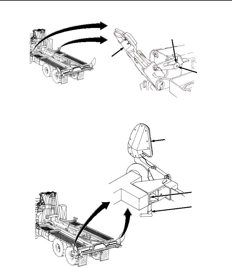
Figure 5.
Setting Front Pin Locks.
10.
Secure curb-side and road-side rear guides (Figure 6, Item 12) in the engaged position:
12
14
13
Figure 6. Setting Rear Guides.
a.
Rotate latch pin (Figure 6, Item 13), and swing rear guide (Figure 6, Item 12) to the intermediate position.
b.
Ensure each latch pin (Figure 6, Item 13) engages hole (Figure 6, Item 14) in rear guide (Figure 6, Item
12).
03/15/2011Rel(1.8)root(opusualwp)wpno(O01056)