
TM 5-3990-263-13&P
0007
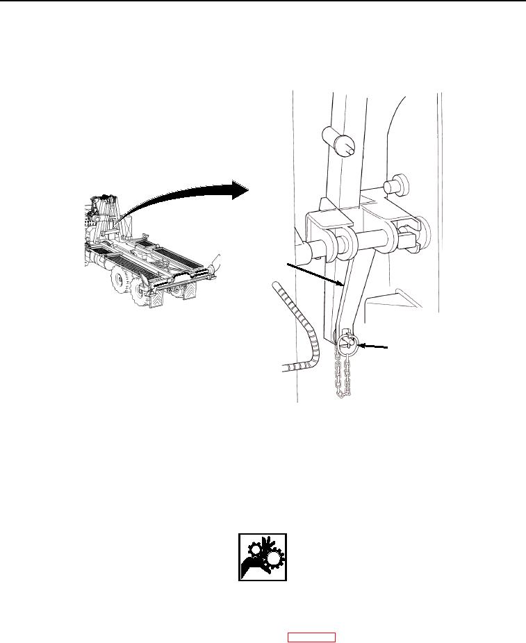
OPERATION - Continued
6.
Secure winch frame to LHS hook arm. Ensure two winch frame locking levers (Figure 4, Item 7) are in the
down position.
7
8
Figure 4.
Lock Winch Frame to LHS Hook Arm.
7.
If locking levers (Figure 4, Item 7) are not down:
a.
Remove lockpin (Figure 4, Item 8) from each upper locking lever (Figure 4, Item 7).
b.
Swing each locking lever (Figure 4, Item 7) to the down position.
c.
Insert lockpin (Figure 4, Item 8) into each locking lever (Figure 4, Item 7).
WARNING
Keep hands and fingers clear of front pin lock assemblies when in the auto engaged and
disengaged position. Failure to comply may result in serious injury or death to personnel.
8.
Secure curb-side and road-side front pin lock assemblies (Figure 5, Item 9) in the auto engage position (refer
to BAP locks checklist for proper position of BAP locks) (WP 0015).
9.
Pull back front pin lock assemblies (Figure 5, Item 9) until latch lever pin (Figure 5, Item 10) rests in base of
vertical slot (Figure 5, Item 11).
03/15/2011Rel(1.8)root(opusualwp)wpno(O01056)