
TM 5-3990-263-13&P
0007
OPERATION - Continued
CAUTION
Do not position PTO ENGAGE switch to ON with HIGH IDLE switch ON. Engaging the
PTO with HIGH IDLE switch ON may result in sudden application of hydraulic pressure
to the LHS. Failure to comply may result in damage to equipment.
PTO ENGAGE switch must be positioned OFF before road transport or severe damage
to equipment may result.
12.
Set PTO ENGAGE switch (Figure 7, Item 16) to ON position. Indicator light (Figure 7, Item 17) will illuminate.
13.
Install remote-control unit (Figure 7, Item 18):
a.
Remove remote-control unit (Figure 7, Item 18) from stowage box (Figure 7, Item 19).
b.
Remove cable (Figure 7, Item 20) from stowage box (Figure 7, Item 19).
c.
Connect cable (Figure 7, Item 20) to curb-side or road-side LHS receptacle (Figure 7, Item 21).
14.
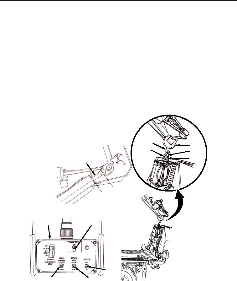
Turn HIGH IDLE switch (Figure 8, Item 22) on remote-control unit (Figure 8, Item 18) to ON position.
29
30
26
31
27
24
s
he )
c
in cm
6 5
(1
18
22
28
25
23
Figure 8.
Picking Up Bridge Bay.
03/15/2011Rel(1.8)root(opusualwp)wpno(O01056)