
TM 5-3990-263-13&P
0008
OPERATION - Continued
2
3
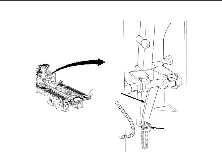
Figure 2. Lock Winch Frame to Hook Arm.
3.
If locking levers (Figure 2, Item 2) are not down:
a.
Remove lockpin (Figure 2, Item 3) from each locking lever (Figure 2, Item 2).
b.
Swing each locking lever (Figure 2, Item 2) to the down position.
c.
Insert lockpin (Figure 2, Item 3) into each locking lever (Figure 2, Item 2).
03/15/2011Rel(1.8)root(opusualwp)wpno(O01057)