
TM 5-3990-263-13&P
0008
OPERATION - Continued
10.
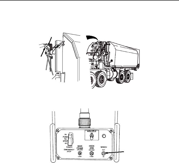
Ensure winch cable hook (Figure 6, Item 16) is securely attached to stationary bay lifting eye (Figure 6, Item
17). Ensure winch cable hook (Figure 6, Item 16) is facing rear with throat up. Refer to TM 5-5420-209-12 or
TM 5-5420-278-10.
17
16
Figure 6.
Check and Set Winch Cable Tension.
11.
Position WINCH switch (Figure 7, Item 18) to IN. Release when tension is applied to winch cable.
18
Figure 7.
Remote Control Unit Switches.
03/15/2011Rel(1.8)root(opusualwp)wpno(O01057)